
Showing posts with label Wemos D1. Show all posts
Showing posts with label Wemos D1. Show all posts
Sunday, 9 February 2020
H4Plugins finally released!
Monday, 15 July 2019
Esparto v3.3 released at last
 AT last! A "quick fix " to patch up a problem in someone else's library has just ended up being a 2-month ground-up rewrite. I am so fed up with the whole thing, I hope you lot all like it enough to cheer me up: Watch the video then go and have a play with it.
Esparto v3.3 released at last. Still some documentation being "backfilled" but the code should be ok and with 61 examples, you should be fine....
AT last! A "quick fix " to patch up a problem in someone else's library has just ended up being a 2-month ground-up rewrite. I am so fed up with the whole thing, I hope you lot all like it enough to cheer me up: Watch the video then go and have a play with it.
Esparto v3.3 released at last. Still some documentation being "backfilled" but the code should be ok and with 61 examples, you should be fine....
Friday, 17 May 2019

Thursday, 28 February 2019
Videos of Esparto v3 in action
Video no 1: Overview and features

Video no 2: The code behind the overview

Video no 2: The code behind the overview
Tuesday, 26 February 2019
Esparto v3 finally released!
Blimey, it's finally done. Esparto v3.0.0 released! (subject to some documentation additions and tweaks) Some fun facts:
281 files in 72 folders totalling 11.8MB
Main code is 16 source files totalling 3742 lines of code
Includes 47 example sketches totalling 3704 lines of code..I'm happy to call it 7500 lines of code...
281 files in 72 folders totalling 11.8MB
Main code is 16 source files totalling 3742 lines of code
Includes 47 example sketches totalling 3704 lines of code..I'm happy to call it 7500 lines of code...

Thursday, 18 October 2018
A "sometimes I amaze myself" soldering repair
I have two TP-LINK powerline extenders (TL-WPA4220) which allow me to have WiFi in the far reaches of my empire. Well in my big barn, at least, one for each end as its 50m long with walls of 0.75m granite. Anyway, voila:

So far so good until a recent flood (about knee deep) and one was fitted low down and got drenched. It was unpowered at the time, so with a little patience and perhaps a hair drier - in theory, at least - all should have been well, because they ain't cheap! The problem with that last statement was the wod "patience" - I have little and thought it was dried out when it obviously wasn't....
Buzz click pop, bad smell and I let the blue smoke out. Because I'm in remote rural France I have to get everything online and delivery is - er, well - "Gallic" let's say. So as well as the cost, it's the inconvenience, and so I thought I'd open 'er up and see if it was maybe just a fuse ha ha. This is what a good one looks like inside - there is a LOT of stuff in there, but pay attention to the expanded section, becuase that's where the problem lay.

 That problem was fairly obvious: in between the big 4.7uF cap on the left and the pale green vertical inductor on the right - and under the tough white rubbery goo keeping some of the high voltage parts safe - something (who knows what?) had gone "pop" in a fairly big way. When I say "fairly big", I mean a) so that it wasn't actually there anymore b) it has taken out the green solder mask underneath and with it, a fair part of the copper track linking it ot the 4.7uF cap. c) the smoked remains of whatever it had been were all over the cap and inductor and inside the case. Even the rubbery goo was blackened. The inductor and cap were so blackened that I didn't know at first what had popped. It was only when I removed them to see if they were still viable that I spotted the disaster zone*. Ironically, both were fine and fully "in spec" and cleaned up fine.


So far so good until a recent flood (about knee deep) and one was fitted low down and got drenched. It was unpowered at the time, so with a little patience and perhaps a hair drier - in theory, at least - all should have been well, because they ain't cheap! The problem with that last statement was the wod "patience" - I have little and thought it was dried out when it obviously wasn't....
Buzz click pop, bad smell and I let the blue smoke out. Because I'm in remote rural France I have to get everything online and delivery is - er, well - "Gallic" let's say. So as well as the cost, it's the inconvenience, and so I thought I'd open 'er up and see if it was maybe just a fuse ha ha. This is what a good one looks like inside - there is a LOT of stuff in there, but pay attention to the expanded section, becuase that's where the problem lay.

 That problem was fairly obvious: in between the big 4.7uF cap on the left and the pale green vertical inductor on the right - and under the tough white rubbery goo keeping some of the high voltage parts safe - something (who knows what?) had gone "pop" in a fairly big way. When I say "fairly big", I mean a) so that it wasn't actually there anymore b) it has taken out the green solder mask underneath and with it, a fair part of the copper track linking it ot the 4.7uF cap. c) the smoked remains of whatever it had been were all over the cap and inductor and inside the case. Even the rubbery goo was blackened. The inductor and cap were so blackened that I didn't know at first what had popped. It was only when I removed them to see if they were still viable that I spotted the disaster zone*. Ironically, both were fine and fully "in spec" and cleaned up fine.
*Spotted the disater zone only after I had taken a scalpel to the white rubber goo to cut away enough to see "what lies beneath". Answer: an empty pad marked "FB1" and the aformentioned bare board and missing copper. All in all, not good, but I hate being beaten. I mean I didn't even know what an FB might be, but I knew I didn't have one "in stock". Turns out its a ferrite bead and it looked as if it was probably an 0603 size...
I'm okay with 0805s but 0603s strike fear into my heart. I had had some recent success with SOD-323 diodes on some blown Wemos D1s and they aren't much diffferent from an 0603, so...

I trawled ebay to try to find some 0603 ferrite beads...and then I thought "Maybe some of my old "junk" boards might have something...long story short - whole house search until I removed a modem card (!) from an ancient PC. It held not just the one bead I'd need but four - which was good news as anyone who has ever dropped / pinged / burned / lost anything that small. So - with the obligatory cocktail stick tip as reference - we have the blank spaces where the FBs used to be and my calipers showing each to be 2.3x1.3mm - actualy slightly(!) larger than the SOD-323, but this has to go into a space I can only just get into!

First, I cleaned off all the soot residue, removed some "erupted" copper trace, flattened the remainder, polished and fluxed and tinned it...I was only going to get one go at this...
Taking a clear photo of the result is pretty much impossible without an industrial microscope, as the scale is so minute, but my best offering follows. Think back to the "good" shot above, remind yourself of this size of this thing and where it has to go back into:


...and it's a marvel I managed at all! So even though it's a terrible shot, it allows us to see several things:

First, you can see some soot still on the white rubber goo and where I had to scalpel it out...Secondly (despite vigorous scrubbing with isopropyl alcohol) the white FB1 legend is still burn-stained. Third, how close I had to get to the 4.7uF cap with my (huge) track repair...
As I look back at this and the good "before" shot, I relaise the original was probably an 0402 size. I'm glad I never saw it - I'd never have dared. Also using the bigger(!) 0603 helps bridge the gap in the blown-out copper track...
No-one, dear reader, was more surprised than moi to find an instant power on, lights cycle, reconnect to the "other end" of the power line adapter and my SSID being broadcast strongly...all as I stood by with fire extinguisher at the ready...
Monday, 27 August 2018
Esparto v2.0 finally released!
Yes, it's "out of the door" at last. After some final "stress" testing and the creation / testing of 32 (yes, thirty-two) example programs, v2.0 finally goes public.
Intervening health problems added 8 months to the date(!) but at last I can now relax somewhat- with a well-earned beer.
Get Esparto v2.0 here at github
Intervening health problems added 8 months to the date(!) but at last I can now relax somewhat- with a well-earned beer.
Get Esparto v2.0 here at github
Monday, 20 August 2018
Esparto V2 almost ready! The new web UI part 6
The lower panel(s)
Run

This is literally where the action happens. Esparto is designed so that commands can come from several sources:
- MQTT topics
- the web UI
- from within the app itself using the "invoke" functio
The first is one of the most common forms of communications between IOT "things" in home automation. You obviously need access to an MQTT "broker" (fancy name for "server", really) either your own or public one. At this very moment, there is no way to enter a username and password - except manually in your own code - so until I get that fixed... your own broker is the best bet. I use mosquitto (which can be found Mosquitto.org download page) on a raspberry Pi.
But don't despair if none of those options are available, you can still do a lot with Esparto through its own UI, or from your own code. Want to change GPIO0 (D3)'s debounce value for example? Either call Esparto.invoke("cmd/pin/cfg/0/15"); or come to this screen, select the cfg option form the dropdown menu, add the /0 to the Topic line and type 15 into the payload field. Then hit "Simulate MQTT" - Esparto's internals that actually "do the business" are called with exactly the same message as they would have received from a genuine MQTT server. Simples.
As commands are received and actioned (from any source) the stats are dynamically updated. Soon - and certainly before release - I shall add "Alexa" as a source because Esparto is fully Alexa-compatible by pretending to be a Belkin WeMo when asked in the right way. All it can do is "turn on "<your device> or "turn off" the same. That's as much as a lot of devices do, anyway.
The "all" source is special one built in to Esparto allowing you to send a single command to all Esparto device on your 'net, as well as addressing each one indvidually by its device name. For example - while not necessarily advised - "all/cmd/reboot" will do exactly what you think it would.
Users can to subscribe to any topic they choose - including # wildcards - when called back in onMQTTConnect (see previous post in the series for a simple example).
In the demo, the user has subscribed to a wildcard topic like so:
  Esparto.subscribe("wild/#",[](vector<string> vs){
        string suit=vs.front();
        Serial.printf("Wilcard handler suit is , card is %s\n",(CSTR(suit)),CSTR(vs.back()));
        if(suit=="hearts" || suit=="clubs" || suit=="diamonds" || suit=="spades"){
          Serial.printf("You chose the %s of %s\n",CSTR(vs.back()),CSTR(suit));
        }
        else Serial.printf("Invalid suit %s\n",CSTR(suit));
    },"cards");
(They also included (not shown) a simpler topic "flash" which they wrote to call the same code as Alexa commands call. So when Alexa is told to "turn on testbed" it has the same effect as MQTT command "testbed/flash/1" for on and ...0 for off. )
He/she has chosen to only allow this wildcard topic from another made-up source "cards" so "testbed/wild/party" won't work, but" cards/wild/animal "will.
And therein lies a slight oddity - and a caution. Esparto cannot predict the billions of permutations that come after ...wild/ - only the user can decide that. Hence for the system to work Esparto not only has to accept anything of that form, it also has to add it to the above table and count it and that has consequences.
The user code in the demo rejects any subtopic except (rather suitably) hearts, clubs, diamonds and spades and would like the payload to be a card from 2 to 10 or J K Q A. Lazily, it doesn't actually validate the payload, but then all it does is parrot ack to you what you send it, so no harm done in this contrived case. In the real world such appalling coding (I should know, I wrote it - deliberately to bring out these points of course) will almost certainly lead to a crash if unexpected, unvalidated input and/or gibberish is fed to any wildcard topic - so be careful. Trust no-one, and validate everything to within an inch of its short life.
Another consequence is that the more wild rubbish you send that Esparto is duty-bound to accept, the longer that list will get, the slower the UI will become until finally Esparto's self-protection mechanisms will cut in and reject everything from all sources until some memory is freed somehow. This will certainly cause erratic behaviour and possible meltdown at the nuclear power plant, so don't do it. If no memory can get freed, then your Esparto app will die a slow lingering death till you want to reboot it. When you do, remember it's your fault, not Esparto's.
While this a shorter section than some others, this pane is probably one of the most useful of Esparto's many features. There is neither the space nor the time to go into detail about each of the commands and new ones are being thought of as I type...
You may find that all the ...dump... options are missing from the final release, as they are 90% used in debugging. It will be done in such a way that even average programmers will be able to hack into the code and just turn on a #define and recompile. They do steal heap though, whic is already in short supply so don't say you haven't been warned. On the other hand if I can trim some fat from elsewhere during my final code tidy, I might leave some/all of them in. Invoke("cmd/watch/this/space"), you might say.
Others are just fun to play with: .../pin/flash/... , .../pin/pwm/... and .../pin/pattern for example/...
Download the release when it's out "soon", edit in your own SSID/password/device name and give all the topics/commands a try - it's what Esparto is for. Or wait 3 minutes for it to give up and go into AP mode then configure it with your phone.
And enjoy it!

- MQTT topics
- the web UI
- from within the app itself using the "invoke" functio
But don't despair if none of those options are available, you can still do a lot with Esparto through its own UI, or from your own code. Want to change GPIO0 (D3)'s debounce value for example? Either call Esparto.invoke("cmd/pin/cfg/0/15"); or come to this screen, select the cfg option form the dropdown menu, add the /0 to the Topic line and type 15 into the payload field. Then hit "Simulate MQTT" - Esparto's internals that actually "do the business" are called with exactly the same message as they would have received from a genuine MQTT server. Simples.
As commands are received and actioned (from any source) the stats are dynamically updated. Soon - and certainly before release - I shall add "Alexa" as a source because Esparto is fully Alexa-compatible by pretending to be a Belkin WeMo when asked in the right way. All it can do is "turn on "<your device> or "turn off" the same. That's as much as a lot of devices do, anyway.
The "all" source is special one built in to Esparto allowing you to send a single command to all Esparto device on your 'net, as well as addressing each one indvidually by its device name. For example - while not necessarily advised - "all/cmd/reboot" will do exactly what you think it would.
Users can to subscribe to any topic they choose - including # wildcards - when called back in onMQTTConnect (see previous post in the series for a simple example).
In the demo, the user has subscribed to a wildcard topic like so:
Esparto.subscribe("wild/#",[](vector<string> vs){ string suit=vs.front(); Serial.printf("Wilcard handler suit is , card is %s\n",(CSTR(suit)),CSTR(vs.back())); if(suit=="hearts" || suit=="clubs" || suit=="diamonds" || suit=="spades"){ Serial.printf("You chose the %s of %s\n",CSTR(vs.back()),CSTR(suit)); } else Serial.printf("Invalid suit %s\n",CSTR(suit)); },"cards");(They also included (not shown) a simpler topic "flash" which they wrote to call the same code as Alexa commands call. So when Alexa is told to "turn on testbed" it has the same effect as MQTT command "testbed/flash/1" for on and ...0 for off. )
He/she has chosen to only allow this wildcard topic from another made-up source "cards" so "testbed/wild/party" won't work, but" cards/wild/animal "will.
And therein lies a slight oddity - and a caution. Esparto cannot predict the billions of permutations that come after ...wild/ - only the user can decide that. Hence for the system to work Esparto not only has to accept anything of that form, it also has to add it to the above table and count it and that has consequences.
The user code in the demo rejects any subtopic except (rather suitably) hearts, clubs, diamonds and spades and would like the payload to be a card from 2 to 10 or J K Q A. Lazily, it doesn't actually validate the payload, but then all it does is parrot ack to you what you send it, so no harm done in this contrived case. In the real world such appalling coding (I should know, I wrote it - deliberately to bring out these points of course) will almost certainly lead to a crash if unexpected, unvalidated input and/or gibberish is fed to any wildcard topic - so be careful. Trust no-one, and validate everything to within an inch of its short life.
Another consequence is that the more wild rubbish you send that Esparto is duty-bound to accept, the longer that list will get, the slower the UI will become until finally Esparto's self-protection mechanisms will cut in and reject everything from all sources until some memory is freed somehow. This will certainly cause erratic behaviour and possible meltdown at the nuclear power plant, so don't do it. If no memory can get freed, then your Esparto app will die a slow lingering death till you want to reboot it. When you do, remember it's your fault, not Esparto's.
While this a shorter section than some others, this pane is probably one of the most useful of Esparto's many features. There is neither the space nor the time to go into detail about each of the commands and new ones are being thought of as I type...
You may find that all the ...dump... options are missing from the final release, as they are 90% used in debugging. It will be done in such a way that even average programmers will be able to hack into the code and just turn on a #define and recompile. They do steal heap though, whic is already in short supply so don't say you haven't been warned. On the other hand if I can trim some fat from elsewhere during my final code tidy, I might leave some/all of them in. Invoke("cmd/watch/this/space"), you might say.
Others are just fun to play with: .../pin/flash/... , .../pin/pwm/... and .../pin/pattern for example/...
Download the release when it's out "soon", edit in your own SSID/password/device name and give all the topics/commands a try - it's what Esparto is for. Or wait 3 minutes for it to give up and go into AP mode then configure it with your phone.
And enjoy it!
Esparto V2 almost ready! The new web UI part 5
The lower panel(s)
Config

Now we start to see the real power of Esparto coming out. It has a configuration system where name/value pairs are automatically saved to SPIFFS (the ESP8266 Flash file system) as soon as they change and persist into the next reboot, i.e become permanent. Well, until the next factory reset, at least.
The demo code has a Latching push button on GPIO0 (Arduino digital pin D3) and a very "noisy" and sensitive sound sensor (i.e. a high number of thousand IOs per second at the slightest cough) on GPIO12 (D6). It also configures the BUILTIN_LED for output. On a Wemos D1 mini that the demo was built on, this is on GPIO2 (D4). The hardware setup looks like this:
void setupHardware(){Esparto.Output(BUILTIN_LED,LOW,HIGH); // start with LED OFFEsparto.Latching(PUSHBUTTON,INPUT,10,buttonPress); // 10ms of debouncingEsparto.Raw(D6,INPUT,[](int s){ Serial.println("Do nothing"); });Esparto.throttlePin(D6,19);
}
I trust your first taste of the "esparto Way" wasn't too shocking or difficult? setupHardware() is equivalent to the standard Arduino-style setup() and you do the same kind of thing here as you would there - almost. You just do it Esparto-stylee - so for instance, no WiFi.begin and delay loops* Esparto is already connecting to your SSID "in the background" to speed things up.
Also you won't see pinMode calls: Esparto knows what mode to set automatically from the type of Esparto SmartPin you define. So really all we have is one line per I/O device, and often that's all you will need. The only "odd" or "tricky" thing is the throttlePin call. We'll get to the strange syntax in a minute, but first, what exactly is "throttling" and why do we need it here?
It is described in great detail in part 3 of this series, so if you want to know more read up on that first, but for now a simple one liner is that the sound sensors fires far more data than any tiny device can easily cope with -Esparto being no exception - so we have to slow it down, or "throttle" it. D6 is our noisy pin, so we tell Esparto only to allow through 19 of the thousands of 1s and 0s per second.
The reason this is such a low figure is explained in the earlier article. Your LED will still flash vaguely in time with your bangin' house or lounge jazz tracks...ish. Now to that weird syntax...
C++ Lambda functions:
See what? If you don't know about these already, ask Mr Google about them because you will quickly come to love them as much as I do. They are particularly good for callbacks and a lot of your code needs to be in callbacks so now is a good time to learn how to use them. If you are already frightened, fear not: you don't have to use them, the old-fashioned way still works. I will show you what that would look like in a moment and I'm sure you will soon be seeing the benefits of the new-fangled way.
What we want is for Esparto to tell us when pin D6 changes and what is has just changed to: a 0 or a 1. So we need to give Esparto a function that returns nothing (void) and takes a single int parameter, which holds the new state when the pin changed. Ordinarily we'd write:
void namedFunction(int s){Serial.println("Do nothing");}
and then our old-fashioned way would be:
Esparto.Raw(D6,INPUT,namedFunction);
But:
- It's more typing
- We have to invent a name for our free-standing "normal" function that doesn't do a whole lot
- namedFunction can live anywhere in your code base. If your code is large and you are anything like me, it can sometimes take a while to find, by which time you forgot where it was called from!
Let's break down the "new" way (it isn't new at all, it's been around since at least 2011)
,[](int s){ Serial.println("Do nothing"); }
[] = this is a lambda function - it has no name
(int s) = same as before, it takes an int parameter called s
{ Serial.println("Do nothing"); } = this is what the function does, its body. any valid C++ code can live inside the body including if/else blocks, other lambdas etc.
Not too painful, I trust? In summary it's a function with no name (an "anonymous function") that is "bolted in" to the place that needs to call it, instead of having to live outside on its own. It has many benefits:
- Less typing
- Less names to remember
- Lives alongside the thing that defined it and needs it: makes code more easy to understand and saves time hunting
- You can do things with it that you would never have dreamt of, like pass it, lock stock and barrel as an object to another function that can then call it on your behalf! That is beyond the scope of this post, though. Ask Mr Google.
I mention these in some detail because a lot of the example code uses them, for all the reasons above, and because I love them. Esparto could not have been written without them. I hope you come to love them too, and soon - they make working with Esparto a breeze and they're not really that tough are they? Welcome to the 21st century!
Why do nothing?
The demo is purely to show the raw LED beating closely-ish in time with either some music, clapping of hands, whistling, dogs howling etc. Since Esparto does all the checking for changes and SmartPins underneath does all the flashing automatically, there is nothing else for our demo code to do. This shows how powerful Esparto is. Ordinarily the lambda is where you would put your special code that makes your app different from the rest. I do exactly that with the Latching button, which starts and stops the LED flashing by calling buttonPress which you haven't seen yet, but is here in all its glory:
void buttonPress(bool hilo){if(!hilo) {uint32_t rate=Esparto.getConfigInt("blinkrate");Esparto.flashLED(rate);}else Esparto.stopLED();}
User-defined config variables:
And in Esparto.getConfigInt("blinkrate"); you now see the Esparto magic starting to happen. I challenge you to look at the screen shot above and guess what happens when you change the value. Go on, have a go!
If you said "I bet the LED starts flashing at the new rate automatically", you're obviously catching on but you'd be wrong. Only because I'm teasing and you haven't yet pressed the pushbutton to start it flashing at the old rate in the first place. If you had already done that then yes, exactly correct: the LED instantly starts flashing at the new rate, well done! It's now no great leap of faith to correctly assume that changing the debounce value will, er, change the debounce value of the Latching button. You are getting a whole lot of functionality for free here.
But there's more: next time you reboot, the value will be brought back - the config system saves the value whenever it changes, you have nothing further to do. The BWF parameter just made up, to play with, does nothing, isn't used anywhere and you can type what you want in there just for the fun of seeing it survive a reboot. If you want real magic, read the next section on the run panel...
Yet more: send the command testbed/flash with a payload of 1 to start and 0 to stop from an MQTT client and guess what - correct the same thing happens as if you had pressed the button physically yourself. The code to make that happen? Here:
void onMqttConnect(void){Serial.printf("T=%d USER SAYS MQTT CONNECTED\n",millis());Esparto.subscribe("flash",[](vector<string> vs){Serial.printf("Doing my thing with %s\n",CSTR(vs.back()));buttonPress(!atoi(CSTR(vs.back())));});
}
Dont worry about the "vector" stuff, that's more C++ magic that is going to make your relationship with Esparto a much more fruitful one and will be covered in the future. For now be happy that you have just avoided 3 months of tearing your hair out and a learning curve like the side of a cliff, while getting an already pretty capable system "for free" from a mere handful of lines of code!
System config variables:
Anything starting with a "~" is a system variable which Esparto relies on to function properly. So:
- never use "~" in your own config names
- while you can put whatever you like in your own variables as long as your code knows what it means, the same cannot be said for system variables
- never change a system variable unless you know what you are doing, and why!
Some system variables are easy to understand and make sense for the user to change. The ones I have chosen to expose for the demo are like that. By the time the full release comes round there will be a lot more, and they won't be as nice. I can safely predict that even when you read the "advanced guide" with a full explanation of what each does, you still won't want / dare / understand how to change them, so - just don't. Ever!
~fb2Ap:
Is the millisecond count for the amount of time to wait for the WiFi to fail to connect before "falling back" to AP mode and offering yourself up to a phone, tablet etc to get in and configure a valid set of WiFi credentials. The demo has 3 minutes = 180,000 microseconds = 180 seconds. You may want less or more: feel free to change it to a sensible value that works for you.
~lh:
Is used to log the value of the heap every second to an MQTT broker, just in case the 3-minute graphs on the system page aren't enough. 1= start, 0= stop. It will publish /testbed/heap with a payload of the value once per second until you stop it, either by changing the value back to 0, publishing testbed/cmd/logheap/0 over MQTT or reading on to the next section on the run panel...
~mqXXX:
Unsurprisingly, the IP address, port and retry failure re-connection interval of your MQTT broker. Some day soon I will add ~mixer and ~mqPass to enable you to connect to an authenticating remote server. Some day...
Don't ask me about (or mess with!) the as-yet-unseen ~jitter variable - it's the plus / minus entropy timing spread adjustment factor to minimise asynchronous collision probability in the autoStats derived timer reset function. It is currently set to 10. Still fancy seeing what happens if you change it to 11? Or 243? No, I hoped not.
*Ever. No delay loops ever. They are bad, they break asynchronous libraries, stop other tasks from running and are generally BAD STYLE. Do not ever use one in an Esparto callback (or at all, in fact) you simply don't need to. If you think you do, trust me, you are wrong. There is always a better way. call Esparto.once(<x mSec delay>, functionToRunSoon); for example. Don't ever call delay(). Need I say it again?
Esparto V2 almost ready! The new web UI part 4
The lower panel(s)
Info

This is mostly self-explanatory but also raises a few points that are well worth knowing if you intend to become an "Esparto Expert".
These are all static values at the heart of the system, some of them permanently, some for example the IP address for this boot of the system only. They cannot be directly changed by the user. For some that can, see the next section.
Hardware Type:
This lets you know what's running "under the hood". It can be any one of these:
- ESP-01 (but why would you bother when there’s…)
- ESP-01S
- Wemos D1
- Wemos D1 mini
- Wemos D1 lite (and thus probably any other ESP8285 device)
- Wemos D1 pro
- NodeMCU 0.9
- SONOFF Basic
- SONOFF S20
- SONOFF SV
Esparto has been tested on all of the above. It will probably run on anything with an ESP-12 in it, but obviously I can't test every single device on the market/ If you want to send me one to try it out and modify if necessary...
Unique Hardware ID:
This is the last 6 digits of the MAC address and is commonly used in new-out-of-the-box scenarios as a default name before choosing your own and setting your SSID / Password credentials the default name of the demo device would be ESPARTO-17D383. See part 2 earlier for more detail on this value and advice renaming your device to replace it.
IP Address:
Need I say more?
Flash Memory Size:
Same as above, except the answer is "Yes".
Esparto weighs in at over 410k - it has a lot of functionality and features. To support OTA updating (and who wouldn't want that?) a "sketch" (app) has to be able to fit into half the available flash size. On smaller devices e.g. the SONOFFs you get 1MB thus 512k is usable if you want OTA (and you do!).
As you can see things are already starting to squeak, so you need to keep your own additional code
small, efficient and light-weight. There is also a very limited amount of heap left. Esparto starts up with about 27k free, and that can go up and down rapidly - see the graphs in part 3 of this series for an example. Keep your heap use to a minimum and guard any heap-using routines with a check in what's free first if you want to avoid crashing (again, you do!).
The good news is that Esparto does so much for you that your own code will be small and consist mostly of short callback routines that Esparto will execute at the relevant time on your behalf. There is no loop() function and no setup() function. You will rapidly get used to doing things the "Esparto Way" once you see how easy it is.
H4 library version number:
If you want to get further than a simple "Blinky" it helps to understand the structure of Esparto. It is built from 3 main libraries, H4, SmartPins and Esparto itself.
H4 which handles all the timer functions, scheduling, task separation and "slip streaming" of asynchronous functions into the synchronous task queue which runs on the main loop. No more WDT resets, no more "volatile"s. When your task runs, it is (almost) the only player in town and the H4 library makes sure you have to try really really hard to break things or upset other tasks.
It comes with 7 of its own examples demonstrating how each and all of its functions work. Esparto "encapsulates" H4, so all of the H4 functions will appear to you as identical Esparto functions, so you do need to understand these first.
SmartPins library version number:
See above. Note the version shown is incorrect - by the time of release it will also be 2.0.0 (actually it is, but I forgot to update the version number field before the demo - my bad!)
SmartPins as its name suggests manages all the input and output pins for you. It is what enables Esparto to give you the fancy real-time flashing LED display for all the pins. It also does everything you could ever want to do with a pin, including debouncing, interrupt handling (although there are good reasons why you would probably never need to use it), rotary decoding and much more.
The Encoder input type lets you manage a rotary with a single line of code - you tell it the name of a variable, and whenever you access the variable it will automagically have the current decoder value in it. One line of code! It's my favourite Esparto feature: most of my own mini-apps have some kind of "tweak" factor using a rotary, it's so easy. Some even have two...at the extra expense of one more line of code...I'll stop now, I think you have got the point.
SmartPins comes with nineteen sample program covering every in and out (literally!) of the many types of input modes it supports. It also has access to all H4's functions and relies on it 100% to function. Pretty much every example has at least one or two H4 features though of course they appear seamlessly as identical SmartPins features.
It is important then to work through the examples in order to fully understand the power and flexibility of Esparto, because in the same way, all Esparto functions are automatically the same as all SmartPins functions.
Even seasoned programmers will benefit, as Esparto works in a very different way from 99.235% of all the thousands of sample sketches you will find online. You need to learn the "Esparto Way", but for those with experience it won't take long at all.
Just as an example, here's the code (with comments removed for brevity) for the simple blinky. "Simple" includes having a fully debounced on/off switch unlike 99.476% of other blinkies.
NOTE:
While H4 and SmartPins both have visible setup() and loop() functions, Esparto does not. There are two reasons for keeping them in:- To make the early examples more readily recognisable and ease you in to the "Esparto Way" and "chunk up" the amount of learning at each stage into bite-sized pieces.
- To enable you to use them on their own without the full Esparto, although I can't think of any reason why you would want to unless you are the kind that likes to make things deliberately hard for themselves
#include <SmartPins.h>

SmartPins smartPins;

void buttonPress(bool hilo){

  if(!hilo) smartPins.flashLED(250);

  else smartPins.stopLED();

}

void setup(){

  Serial.begin(74880);

  Serial.println("LED will change state (flashing/off) on each separate button up/down press");

  smartPins.Output(BUILTIN_LED);

  smartPins.Latching(0,INPUT,15,buttonPress); // GPIO 0 + 15ms of debouncing

}

void loop(){

  smartPins.loop();

}
I hope you will agree both that it's pretty easy and also that you get "a lot for your money" for very little coding effort. That principle underlies the whole of the "Esparto Way": Esparto does 90% of the "heavy lifting", you plug in the remaining 10% which is specific to your IOT / home automation app. Esparto allows you to concentrate on just the code that's important to you - all the hard stuff "just works"
NBoot & Code:
These may be the first indication of a (hopefully very rare) problem. NBoot is the number of times this device has been rebooted and "Code" is the reason why. If it has just been freshly programmed then (as has the demo device) then it will read ESPARTO_BOOT_UNCONTROLLED.
What this means is that it was not shut down by user action, but forcibly rebooted, as the IDE does. You will also see this code if the device crashes for any reason.
If you click the Reboot button,. the code will become ESPARTO_BOOT_UI. If you send an MQTT command e.g. testbed/cmd/reboot the code becomes ESPARTO_BOOT_MQTT and son on, although obviously you will replace "testbed" with your own device name first.
If you see an increased boot count and a reason you don't expect - something has gone wrong!
The "tXXX" values:
These measure the amount of milliseconds since boot up when:
tHW:
The time after which your sensors, buttons, relays, remote controlled Gatling guns etc become ready to run. One of the fundamental design goals of Esparto is that your hardware should operate a) as early as possible b) whether you have a WiFi connection or not c) all the time, always.Even if - as happens in the real world - bugs occur and the occasional crash occurs, your hardware will be back up ready to go in about 125 milliseconds. Impressive, non? It's one of the reason behind why Esparto won't let you play with setup() and loop(): it has quite a bit of complex setup of its own to do, and it has to happen fast, and in a very specific order.
tWiFi:
The time after which you can load up the web UI because your device now has a valid IP address.tMQTT:
Similarly, the time after which Esparto is actively listening for MQTT commands, both its own any any that you choose also to listen for. All Esparto command start with "cmd", so you must not use this in any of your own topics, or who knows when that Gatling gun may go off in error?High values of either tWiFi or tMQTT may be early indications of problems with your router, network or MQTT broker. Or they may just be a sign of a slow network - only you will know. Personally, I'd worry about anything much more than the demo values. Again, I think 3.2 secs from power on to receiving MQTT commands is "in the zone".
Sunday, 19 August 2018
Esparto V2 observation on AsyncWebSocket performance and limits
Esparto V2 nears completion! During the final testing I had some problem with crashes, and traced it to a high rate of writes to the AsyncWebSocket. If the user requests socket writes faster than the browser can consume them a queue / backlog builds up and the free heap decreases rapidly until...bang!
That's no great surprise, but it may help other folk to know what the limit is. Bear in mind that the following examples were deliberately throwing a sustained rate of writes with no pause for recovery. In the normal course of events where socket writes are fairly random, there won't be so much of an issue. My app sends socket writes to flash the pins on and off in "real time" and also updates the sliding graphs, the UpTime and the pusling heartbeat. So there is a continual "background" of 3/sec even with no GPIO pin activity.
If you connect a noisy sensor to an input pin (e.g. a sound sensor that fires thousands of pin transitions per second) a crash is the obvious result and so each pin can be "throttled" to avoid problems. It was in trying to find a "safe" throttling value that I generated the graph and I hope others will find it useful.
As can be seen, once past about 21 writes/sec, things go down hill rapidly (but predictably). If your app does not have heap protection and/or throttling then you are going to run into problems if you sustain more than that amount. If you know your free heap then the graph will allow you to calculate what rate is safe for any given period.
For example, say you start with 30k free heap. Some part of your code fires a burst of socket writes at 50 per second. Reading up from 50 and then back to the vertical axis you will see that about 2kb heap per second will be consumed, giving you 30 / 2 = 15 seconds before you crash.
If you can organise your app so that it backs off before that time and allows the heap to recover back to 30k then you can safely repeat the process.
Also you can see that once the rate drops, the heap recovers rapidly, so bear this in mind when designing you app and try to minmise socket writes.
I created a lot of problems for myself early on by trying to load the whole UI as a monlithic block, with 40,50, 60 or more socket writes to set it up as soon as the socket opened. Trying to get round this problem led me to the rate throttling method I now use, thanks to the data behind this post.
A technique I use to update all four sliding graphs (1x per sec) as well as the current, min and max figures for each graph is by combing all those values into a single write and allowing the browser Javascript to parse, spilt and distribute them accordingly.
Another technique is to build in pauses between groups of writes. I use "lazy loading" of the web UI. It loads in 5 sections, each doing a chunk of work then scheduling the next chunk a short while later. The "short while" is of course calculated using the above graph! Yes, this makes the UI a little slow to load, but it doesn't crash!
Further, only the "active panel" is loaded on inital AsyncWebServer request. In my case it's the WiFi configuration panel (curently hidden behind the graph panel) . Each of the six icons at the top left of the lower panel will cease any socket activity to the current panel, hide it, show the new panel over the top and start any dynamic updating with socket writes for the new panel. Thus socket writes are only sent for the panel that is currently visible.
For further info feel free to contact me @ esparto8266 -at- gmail.com
That's no great surprise, but it may help other folk to know what the limit is. Bear in mind that the following examples were deliberately throwing a sustained rate of writes with no pause for recovery. In the normal course of events where socket writes are fairly random, there won't be so much of an issue. My app sends socket writes to flash the pins on and off in "real time" and also updates the sliding graphs, the UpTime and the pusling heartbeat. So there is a continual "background" of 3/sec even with no GPIO pin activity.
 |
| Esparto V2 web UI, dynamically updating system panel running on Wemos D1 min |
If you connect a noisy sensor to an input pin (e.g. a sound sensor that fires thousands of pin transitions per second) a crash is the obvious result and so each pin can be "throttled" to avoid problems. It was in trying to find a "safe" throttling value that I generated the graph and I hope others will find it useful.
 |
For example, say you start with 30k free heap. Some part of your code fires a burst of socket writes at 50 per second. Reading up from 50 and then back to the vertical axis you will see that about 2kb heap per second will be consumed, giving you 30 / 2 = 15 seconds before you crash.
If you can organise your app so that it backs off before that time and allows the heap to recover back to 30k then you can safely repeat the process.
Also you can see that once the rate drops, the heap recovers rapidly, so bear this in mind when designing you app and try to minmise socket writes.
I created a lot of problems for myself early on by trying to load the whole UI as a monlithic block, with 40,50, 60 or more socket writes to set it up as soon as the socket opened. Trying to get round this problem led me to the rate throttling method I now use, thanks to the data behind this post.
A technique I use to update all four sliding graphs (1x per sec) as well as the current, min and max figures for each graph is by combing all those values into a single write and allowing the browser Javascript to parse, spilt and distribute them accordingly.
Another technique is to build in pauses between groups of writes. I use "lazy loading" of the web UI. It loads in 5 sections, each doing a chunk of work then scheduling the next chunk a short while later. The "short while" is of course calculated using the above graph! Yes, this makes the UI a little slow to load, but it doesn't crash!
Further, only the "active panel" is loaded on inital AsyncWebServer request. In my case it's the WiFi configuration panel (curently hidden behind the graph panel) . Each of the six icons at the top left of the lower panel will cease any socket activity to the current panel, hide it, show the new panel over the top and start any dynamic updating with socket writes for the new panel. Thus socket writes are only sent for the panel that is currently visible.
For further info feel free to contact me @ esparto8266 -at- gmail.com
Wednesday, 8 August 2018
ESP8266 music-driven flasher in only 6 lines of code!!! (Part 1)
Firstly, I must apologise for having been away so long - I had a little medical problem. (Well, not so little...). What is little though is the number of lines you need to get a fully functional and stable ESP8266 / Arduino project off the ground using my "Esparto" library (of which more later)
Let's see it working. Second apology: I'm sorry about the distracting voiceover on the video but I discovered that Facebook recognises audio content and mutes them if it detecs copyrighted content! It's both unnerving and clever. Since I chose David Bowie's "China Girl" for the demo, I fell foul of the rule, of which - up until that point - I was blissfully unaware! I broke the system by talking loudly over it and re-uploading.
Now I guess that flashing LEDs on ESP8266s are not a new thing, but the whole point of the demo is this, which I hope is more surprising:
There's not much to explain, the pinMode does what the standard Arduino pinMode does, and a little bit more. The two extra parameters tell Esparto when the pin is "active" i.e. what binary state constitues "on" and what its inital state should be, thus saving you the digitalWrite. It defaults to LED_BUILTIN and on many dev boards it is active LOW, i.e. when you write 0 its turns on and goes off when you write 1. So here, we tell it to start "off" which is HIGH for the LED_BUILTIN on a Wemos D1, If that's confusing, I agree, but Esparto worries about all that for you. The Esparto.pinMode defaults are ...,HIGH, LOW); for "normal" LEDs so if yours is one of those just write: Esparto.pinMode(MY_LED,OUTPUT); as you would do normally, where MY_LED is set to your chosen active HIGH "normal" pin.
The next line is where the action happens - all of it. The syntax may look a) new b) odd c) horrible, and if you don't know what a C++ "lambda function is, look it up now. A good explanation can be found here. You don't need one for Esparto, the name of an ordinary function will do e.g. onPinChange - but using the lambda saves you having to write a whole extra function whose core is juist one line - in this case pulseLED.
Esparto's pulseLED does exactly what it says on the tin: it pulses or "blips" an output pin for a given number of milliseconds. In our case we choose just one millisecond which may seem as if its going to be waaay to short for our eyes to see. The sound sensor - when calibrated correctly - is going to be throwing binary 1s and 0s into pin D6 faster than you can dream of so when you "stack up" a lot of 1ms pulse into a second you get...well, you have seen the video!
So this weird "lambda" thing just calls pulseLED and because we have used the "raw" version of Esparto's many input pin types, we will get every* flicker. The pin value is passed to the lambda (or your own function) every time it changes* in the v parameter. So we filter out only the 1s (a bit like a RISING interrupt - if you know what that is - and a forthcoming blogpost will explain why with Esparto, 99% of the time you don't need to).
If it makes you feel easier, the following does exactly the same:
It's just that the lambda version allows me to make the (much more) astounding claim of "...in only 6 lines"! Well worth the effort, I thought.
And that's all there is to it. If you are not impressed, then think of this:
If you change the Esparto line to: ESPArto Esparto(yourSSID.yourPWD); a number of wonderful things occur.
Firstly, you will be abe to see a webserver running on your tiny device that allows you to watch the pins flash on and off, reconfigure itself in numerous ways and even simulate receiving MQTT commands...Oh, I almsot forgot: it responds to Amazon's Alexa.
If that sounds all a little too flashy(1) then be aware you can also flash any LED with just 1 line: flashLED(1000,myPin) for example. Or flash a series of pulses in PWM style, e.g. flashLED(1000,25, myPin) will give a 250ms pulse (25% of 1000) every 1sec (1000ms). Enough? What about flashing a repetetive pattern such as S-O-S in morse code? Yes, you guessed it: flashLED("... --- ...",myPin). You can even have many LEDs all flashing at different rates, patterns etc without any problems and with only a few lines of code.
If a raw pin is no use to you, choose from:
*as long as it happens no less than 120 microseconds after the previous one...a forthcoming article will explain this and why using notoriously tricky interrupts may well be a thing of the past since Esparto
Let's see it working. Second apology: I'm sorry about the distracting voiceover on the video but I discovered that Facebook recognises audio content and mutes them if it detecs copyrighted content! It's both unnerving and clever. Since I chose David Bowie's "China Girl" for the demo, I fell foul of the rule, of which - up until that point - I was blissfully unaware! I broke the system by talking loudly over it and re-uploading.
Now I guess that flashing LEDs on ESP8266s are not a new thing, but the whole point of the demo is this, which I hope is more surprising:
#include <ESPArto.h>

ESPArto Esparto;

void setupHardware(){

    Esparto.Output(LED_BUILTIN,LOW,HIGH);

    Esparto.Raw(D6,INPUT_PULLUP,[](int v){ if(v) Esparto.pulseLED(1); });

}
No, there is nothing missing: that's the whole code! And it "just works" as you can see from the video. Yes, there is no setup() function and no loop() function. Esparto takes care of all of that. It manages the whole of the ESP8266 hardware (with all its complexities and traps waiting for the unwary beginner) and calls your code only when it is safe to do so. This means no more random crashes, WDT resets and other common "gotcha"s.There's not much to explain, the pinMode does what the standard Arduino pinMode does, and a little bit more. The two extra parameters tell Esparto when the pin is "active" i.e. what binary state constitues "on" and what its inital state should be, thus saving you the digitalWrite. It defaults to LED_BUILTIN and on many dev boards it is active LOW, i.e. when you write 0 its turns on and goes off when you write 1. So here, we tell it to start "off" which is HIGH for the LED_BUILTIN on a Wemos D1, If that's confusing, I agree, but Esparto worries about all that for you. The Esparto.pinMode defaults are ...,HIGH, LOW); for "normal" LEDs so if yours is one of those just write: Esparto.pinMode(MY_LED,OUTPUT); as you would do normally, where MY_LED is set to your chosen active HIGH "normal" pin.
The next line is where the action happens - all of it. The syntax may look a) new b) odd c) horrible, and if you don't know what a C++ "lambda function is, look it up now. A good explanation can be found here. You don't need one for Esparto, the name of an ordinary function will do e.g. onPinChange - but using the lambda saves you having to write a whole extra function whose core is juist one line - in this case pulseLED.
Esparto's pulseLED does exactly what it says on the tin: it pulses or "blips" an output pin for a given number of milliseconds. In our case we choose just one millisecond which may seem as if its going to be waaay to short for our eyes to see. The sound sensor - when calibrated correctly - is going to be throwing binary 1s and 0s into pin D6 faster than you can dream of so when you "stack up" a lot of 1ms pulse into a second you get...well, you have seen the video!
So this weird "lambda" thing just calls pulseLED and because we have used the "raw" version of Esparto's many input pin types, we will get every* flicker. The pin value is passed to the lambda (or your own function) every time it changes* in the v parameter. So we filter out only the 1s (a bit like a RISING interrupt - if you know what that is - and a forthcoming blogpost will explain why with Esparto, 99% of the time you don't need to).
If it makes you feel easier, the following does exactly the same:
...

void onPinChange(int v){

if(v){
  smartPins.pulseLED(1);
  }
}

...

Esparto.Raw(D6,INPUT_PULLUP,onPinChange);
...
It's just that the lambda version allows me to make the (much more) astounding claim of "...in only 6 lines"! Well worth the effort, I thought.
And that's all there is to it. If you are not impressed, then think of this:
If you change the Esparto line to: ESPArto Esparto(yourSSID.yourPWD); a number of wonderful things occur.
Firstly, you will be abe to see a webserver running on your tiny device that allows you to watch the pins flash on and off, reconfigure itself in numerous ways and even simulate receiving MQTT commands...Oh, I almsot forgot: it responds to Amazon's Alexa.
If that sounds all a little too flashy(1) then be aware you can also flash any LED with just 1 line: flashLED(1000,myPin) for example. Or flash a series of pulses in PWM style, e.g. flashLED(1000,25, myPin) will give a 250ms pulse (25% of 1000) every 1sec (1000ms). Enough? What about flashing a repetetive pattern such as S-O-S in morse code? Yes, you guessed it: flashLED("... --- ...",myPin). You can even have many LEDs all flashing at different rates, patterns etc without any problems and with only a few lines of code.
If a raw pin is no use to you, choose from:
- Debounced
- Encoder
- EncoderAuto
- Latching
- Polled
- Reporting
- Retriggering
- Timed
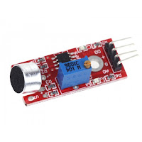
One important point to note is to power it from the 3.3v rail. NOT the 5v! Connect the lead labelled DO (Digital Output) to your chosen pin on your ESP8266, nodeMCU etc - Esparto works on pretty much any dev board with an ESP-12 module on it. The demo uses a Wemos (now LOLIN) D1 mini and I chose GPIO12 which is Arduino digital D6 and turn the music up LOUD! Seriously, those cheap sensors are not very sensitive and you will need to be very close to the speaker. Also, you will have to calibrate the sensor by twiddling the tiny trimpot until it is just on the edge of going wild...then sit back and enjoy.
In part 2, we will look at a slightly more advanced version that a) uses a different technique from Esparto's built-in pulseLED function and b) uses a rotary encoder to "tweak" the LED response for a much more subtle and pleasing effect. Don't worry, as you may expect by now, its only a few extra lines.
*as long as it happens no less than 120 microseconds after the previous one...a forthcoming article will explain this and why using notoriously tricky interrupts may well be a thing of the past since Esparto
Friday, 10 November 2017
Automatic unattended update of ESP8266 firmware using http server
One of the design goals for my home automation system was to be able to performs OTA (over-the-air) updates. The Arduino IDE makes this very easy, but when you have many devices deployed, it becomes a trifle tedious.
An easier way is to run and "update server" on your network and have each device check at boot time (or via an MQTT message) whether a newer version exists and if so, update itself automatically.
The central issue then is building the update server. The server software, language etc are unimportant: it's the logic of how it responds to the request that matters. The excellent ESP8266httpUpdate class makes it very simple.
My own server is a "flow" in my NODE-RED controller on a raspberry Pi and - as you will see shortly - the logic is actually very simple.
What makes this all possible is the extra "headers" that the ESP8266HTTPUpdate class adds to the outgoing http request. They allow a great deal of control (should you need it) over how each device is updated.
x-ESP8266-STA-MAC
x-ESP8266-AP-MAC
x-ESP8266-free-space
x-ESP8266-sketch-size
x-ESP8266-sketch-md5
x-ESP8266-chip-size
x-ESP8266-sdk-version
x-ESP8266-mode set to either "spiffs" or "sketch"
x-ESP8266-version
This information allows the server to check that the upload will fit into the requesting device's memory, or provide a specific binary for a specific chip using the unique MAC address. Note also that you can also update a SPIFFS image (e.g. you inbuilt web pages / images scripts etc). The most important item is the version. This can be anything you decide.
The simple protocol and logic is this:
Device: "Hi, I'm firmware version a.b.c, do you have a newer version?"
Server: "Let me see...ah yes I have a.b.d - here it comes..."
If a newer version does exists the server just sends it as a load of binary data in the http reply. The ESP8266httpUpdate class does the tricky part of copying the binary into memory, changing the firmware boot address to the new code than (if requested) rebooting the device to run the new coded
If on the other hand there is no higher version, it replies with a http 304 error which effectively says: "I have nothing for you" and your code continues to run as normal.
Here's my NODE-RED update flow which shows the simplicity of it:
 The salmon pink "nodes" are functions written in javascript - before delving into the actual code (which is minimal) we need to talk a little more about my setup:
On my server, I have a folder called /home/pi/trucFirmware which contains:
-rw-r--r-- 1 pi pi 65536 Nov 7 10:22 spiffs_0_4_3_1M.bin
-rw-r--r-- 1 pi pi 1028096 Nov 7 10:22 spiffs_0_4_3_4M.bin
-rw-r--r-- 1 pi pi 352192 Oct 17 13:37 truc_0_4_0.ino.d1_mini.bin
-rw-r--r-- 1 pi pi 344336 Oct 17 13:34 truc_0_4_0.ino.esp01s.bin
-rw-r--r-- 1 pi pi 352208 Oct 17 13:39 truc_0_4_0.ino.nodemcu.bin
-rw-r--r-- 1 pi pi 344528 Oct 17 13:35 truc_0_4_0.ino.sonoff_basic.bin
-rw-r--r-- 1 pi pi 347552 Oct 17 13:36 truc_0_4_0.ino.sonoff_sv.bin
-rw-r--r-- 1 pi pi 348144 Nov 9 17:46 truc_0_4_3.ino.sonoff_basic.bin
I maintain a separate binary for each hardware type (from a single source file with a few #defines) and when a new release is ready I use the Arduino IDE "sketch/Export compiled Binary" menu command for each target device.
Note that even though there are 5 different hardware types, there are only two SPIFFS binaries: a 1M and a 4M version - constructed with the mkspiffs tool - since all the devices have either 1M or 4M flash.
Once you have the mkspiffs tool, building the spiffs is simple. I have a one-line batch file for the 1M version which takes the version number as a parameter (%1)
mkspiffs -c data/ spiffs_%1_1M.bin
and another for the 4M version:
mkspiffs -p 256 -b 8192 -s 0x0FB000 -c data/ spiffs_%1_4M.bin
I then copy all the compile binaries and the SPIFFS .bin files over to /home/pi/trucFirmware
The whole process then, goes like this:
The sketch contains the following code:
When I'm ready, I call _actualUpdate(true); and the action then moves to the server:
The first node in the diagram above "listens" for an http request to url http://192.168.1.4:1880/update with the device type appended. It passes this to "Construct search path" function node which has the following javascript code:
This just sets up the appropriate path with wildcard for the sys function which follows, which simply runs ls - r <msg.payload>
The output is then fed to the "Compare versions" function node:
There you have it: automatic unattended updates. All you need to do is copy the new binaries to your sever and - voila! - the rest "just happens". It certainly makes my life easier with 8x ESP-01S, 6x Wemos D1, 4x Sonoff Basic 10x Sonoff S20, 2x Sonoff SV and a NodeMCU - 31 devices in all to update when I make a code change.
Doing is this way is almost effortless.
An easier way is to run and "update server" on your network and have each device check at boot time (or via an MQTT message) whether a newer version exists and if so, update itself automatically.
The central issue then is building the update server. The server software, language etc are unimportant: it's the logic of how it responds to the request that matters. The excellent ESP8266httpUpdate class makes it very simple.
My own server is a "flow" in my NODE-RED controller on a raspberry Pi and - as you will see shortly - the logic is actually very simple.
What makes this all possible is the extra "headers" that the ESP8266HTTPUpdate class adds to the outgoing http request. They allow a great deal of control (should you need it) over how each device is updated.
x-ESP8266-STA-MAC
x-ESP8266-AP-MAC
x-ESP8266-free-space
x-ESP8266-sketch-size
x-ESP8266-sketch-md5
x-ESP8266-chip-size
x-ESP8266-sdk-version
x-ESP8266-mode set to either "spiffs" or "sketch"
x-ESP8266-version
This information allows the server to check that the upload will fit into the requesting device's memory, or provide a specific binary for a specific chip using the unique MAC address. Note also that you can also update a SPIFFS image (e.g. you inbuilt web pages / images scripts etc). The most important item is the version. This can be anything you decide.
The simple protocol and logic is this:
Device: "Hi, I'm firmware version a.b.c, do you have a newer version?"
Server: "Let me see...ah yes I have a.b.d - here it comes..."
If a newer version does exists the server just sends it as a load of binary data in the http reply. The ESP8266httpUpdate class does the tricky part of copying the binary into memory, changing the firmware boot address to the new code than (if requested) rebooting the device to run the new coded
If on the other hand there is no higher version, it replies with a http 304 error which effectively says: "I have nothing for you" and your code continues to run as normal.
Here's my NODE-RED update flow which shows the simplicity of it:
On my server, I have a folder called /home/pi/trucFirmware which contains:
-rw-r--r-- 1 pi pi 65536 Nov 7 10:22 spiffs_0_4_3_1M.bin
-rw-r--r-- 1 pi pi 1028096 Nov 7 10:22 spiffs_0_4_3_4M.bin
-rw-r--r-- 1 pi pi 352192 Oct 17 13:37 truc_0_4_0.ino.d1_mini.bin
-rw-r--r-- 1 pi pi 344336 Oct 17 13:34 truc_0_4_0.ino.esp01s.bin
-rw-r--r-- 1 pi pi 352208 Oct 17 13:39 truc_0_4_0.ino.nodemcu.bin
-rw-r--r-- 1 pi pi 344528 Oct 17 13:35 truc_0_4_0.ino.sonoff_basic.bin
-rw-r--r-- 1 pi pi 347552 Oct 17 13:36 truc_0_4_0.ino.sonoff_sv.bin
-rw-r--r-- 1 pi pi 348144 Nov 9 17:46 truc_0_4_3.ino.sonoff_basic.bin
I maintain a separate binary for each hardware type (from a single source file with a few #defines) and when a new release is ready I use the Arduino IDE "sketch/Export compiled Binary" menu command for each target device.
Note that even though there are 5 different hardware types, there are only two SPIFFS binaries: a 1M and a 4M version - constructed with the mkspiffs tool - since all the devices have either 1M or 4M flash.
Once you have the mkspiffs tool, building the spiffs is simple. I have a one-line batch file for the 1M version which takes the version number as a parameter (%1)
mkspiffs -c data/ spiffs_%1_1M.bin
and another for the 4M version:
mkspiffs -p 256 -b 8192 -s 0x0FB000 -c data/ spiffs_%1_4M.bin
I then copy all the compile binaries and the SPIFFS .bin files over to /home/pi/trucFirmware
The whole process then, goes like this:
The sketch contains the following code:
#include<esp8266httpupdate.h>
...
#define TRUC_VERSION "0_4_99"
// THIS_DEVICE is set earlier depending on various compile-time defines
// which eventually define the hw type, e.g. #define THIS_DEVICE "d1_mini"
const char * updateUrl="http://192.168.1.4:1880/update/"THIS_DEVICE;
// this is my raspberry Pi server, the 1880 is the default NODE-RED port
// /update is the url I chose for the server to "listen" for, followed by the device type
...
bool ICACHE_FLASH_ATTR  _actualUpdate(bool sketch=false){
    String msg;
    t_httpUpdate_return ret;

    ESPhttpUpdate.rebootOnUpdate(false);
    if(sketch){
      msg="sketch";
      ret=ESPhttpUpdate.update(updateUrl,TRUC_VERSION);     // **************** This is the line that "does the business"
    }
    else {
      msg="SPIFFS";
      ret=ESPhttpUpdate.updateSpiffs(updateUrl,CSTR(E.getSPIFFSVersion()));
    }
    if(ret!=HTTP_UPDATE_NO_UPDATES){
      if(ret==HTTP_UPDATE_OK){
        msg.concat(" upgraded");
        Esparto.publish("update",CSTR(msg));
        return true;
        }
      else {
        if(ret==HTTP_UPDATE_FAILED){
          msg.concat(" upgrade FAILED code:");
          msg.concat(ESPhttpUpdate.getLastError());
          msg.concat(" reason:");
          msg.concat(CSTR(ESPhttpUpdate.getLastErrorString()));
          Esparto.publish("update",CSTR(msg));
          }
        }
      }
  return false;
}
When I'm ready, I call _actualUpdate(true); and the action then moves to the server:
The first node in the diagram above "listens" for an http request to url http://192.168.1.4:1880/update with the device type appended. It passes this to "Construct search path" function node which has the following javascript code:
msg.type=msg.req.params.type;
var h=msg.req.headers;
msg.version=h["x-esp8266-version"];

msg.mode=h["x-esp8266-mode"];
if(msg.mode=="sketch"){
    msg.payload="/home/pi/trucFirmware/*.ino."+msg.type+".bin";
}
else {
    var sz=h['x-esp8266-chip-size'];
    msg.payload="/home/pi/trucFirmware/spiffs_*_"+(sz/1048576)+"M.bin";
}
return msg;
This just sets up the appropriate path with wildcard for the sys function which follows, which simply runs ls - r <msg.payload>
The output is then fed to the "Compare versions" function node:
var f=msg.payload.split("\n")[0];
msg.filename=f;

if(msg.mode=="sketch"){
    f=f.replace("/home/pi/trucFirmware/truc_","");
    f=f.replace(".ino."+msg.type+".bin","");
}
else {
    f=f.replace("/home/pi/trucFirmware/spiffs_","");
    f=f.replace(/_\dM\.bin/,"");
}

if(msg.version<f){
    node.warn("upgrade required");
    node.warn("will return "+msg.filename);
    return msg;
}
node.warn("no upgrade");
msg.statusCode=304;
msg.payload=[];

return msg;
The switch node then ensures that either the 304 "no update needed" message is sent or the actual new binary is returned and sent back to the device.There you have it: automatic unattended updates. All you need to do is copy the new binaries to your sever and - voila! - the rest "just happens". It certainly makes my life easier with 8x ESP-01S, 6x Wemos D1, 4x Sonoff Basic 10x Sonoff S20, 2x Sonoff SV and a NodeMCU - 31 devices in all to update when I make a code change.
Doing is this way is almost effortless.
Thursday, 2 November 2017
A bit cheeky...
I recently bought some of these AC-DC converters from ITEAD to run my truc devices from the mains. Mainly they are Wemos D1s but I also decided to build smart wall switches using ESP-01S as they are very small - but they run on 3.3v.


Click here to buy them yourself
"No problem...", I thought - "...looks like they do 3.3v too - bonus!". If you follow the link above to buy one, you'll see that ITEAD's latest photo has no 3.3v pin any more and on closer inspection of my own units, I can see why:
Seems that they are economising the few extra cents per unit of a 3.3v LDO...To be fair to them, the unit is clearly advertised as 5v and that's what I bought it for, but I couldn't help thinking "a ha'porth of tar..."
I also couldn't help thinking that if I could buy a few cheap LDOs in SOT-89 format with the right pinout, then I could right this "wrong". Don't misunderstand me, I'm very happy with ITEAD products and I have bought a lot of them - I trust them and I highly recommend this one, but...you know what I mean?
Anyways, it took a little research to find the right part, and as usual (I get the majority of my components from ebay.com) I found a seller doing five AP1117Y33L (here) They are incorrectly tagged as "Diodes" - but that's half the fun of ebay isn't it? Either way, they are what I needed.
There's a whacking great cap on the input side (470uF) but - as you can see - none on the output side. The datasheet for the AP1117Y33L states it needs a 22uF cap on the output for stability. So as long as I hook one up there on the final board, I should be "quids in".
Now all I have to do is a) bemoan my failing eyesight and b) get the fine tip on my soldering iron and "bite the bullet". If you aren't a big fan of soldering SMD parts ("fiddly" ain't the word), look away now...
I shall report back in due course.
Wednesday, 1 November 2017
Esparto v2.0 - sneak preview: Inside
"A picture is worth..." as they say:
The following 21 lines (one of which is a comment...) are all you need to turn a Sonoff Basic, S20 or SV into an MQTT device with a web interface...etc etc as described in the previous post "...outside". If you don't want diagnostics, you can lose the Serial,begin and cut another line.
The Sonoffs have a push button on GPIO0 and a mains relay on GPIO12. That's all they have, hardware-wise
And the code above is all they need, and I ask you: "What could be simpler?"
True, you will have to physically FLASH upgrade it first time with a FTDI adapter, but after that, Esparto will update itself automatically as needed. It will appear on your WiFi network as esparto666.local and respond to an MQTT "switch" command, by toggling the power relay and will reply with an MQTT "state" message with a payload of "ON" or OFF". It will reconnect after any network failure and all the while, the manual button will still turn it on an off.
Plus it's inside your own network. No snazzy (but often rubbish) App to download. No security problems. No worrying if XYZ corp go out of business and close their cloud, that your lights will never work again...If you can use a web browser, you can control it. If you have an MQTT server, you can control it in much more detail. If you have a NODE-RED server, you can start to do really clever things with your whole house.
Let's look inti the code in more detail (shouldn't take long)
It doesn't look much like a typical Arduino sketch. There is no setup() function and no loop function. Esparto takes care of both, to make sure things are done in the "right" order and to prevent your code from accidentally breaking things or stopping it working.
Your code is all driven asynchronously by Esparto using callbacks. If you don't know what that means, you need to read the sidebar articles under "Essential Information". It starts with setupHardware. This is where you do what you'd normally do in setup. Having said that, much of what you'd "normally do" isn't needed any more.
Tells Esparto that you want the button on GPIO0 debounced (for 15ms) and to call buttonPressed when someone pushes it or lets it go - i.e. when it changes. When it goes HIGH (the button on a Sonoff is "reversed" in sense: it goes LOW when you press it and HIGH when released) the relay is set to the opposite of what it is now. If its already on, it goes off etc - and that is the same as the standard firmware that it comes with when you buy it.
When Esparto has established a valid MQTT connection it calls onMqttConnect. Here, your code tells Esparto you want to receive "switch" topic message and when it gets one, it will call your code in mqttSwitch. As for a button press, you call toggleRelay which then publishes the current switch state to MQTT.
"And that's that"...as they also say.
Adding sensors to a "homebrew" board and adding lots of functionality on top of this is going to get more complex of course, but Esparto is designed to take a lot of the hard work out of that process too. It has a lot of "Hooks" where you can add callbacks in exactly the places you need to create a new "layer" of your own HA system on top of Esparto. That's how my own Chez Toi ioT system works: 90% of the code in each device is Esparto. Esparto has 9 different types of input pin it can manage for you, including rotary encoders and each of those only require one or two lines of code.
As an example my truc firmware when I fisrt wrote it was about 1200 lines of (pretty hairy) code and a lot of bugs. Now it handles GPIO on every pin of a WemosD1 and runs temperature PIR, sound, light, button and touch sensors. It also controls 433MHz RF switches, and it auto-updates itself. It's far more robust, easier to control and has two web pages (one of which is a live GPIO view) when the old one had only one very basic config page. Using Esparto, its only about 300 lines long and most of those 300 lines are a lot simpler and a lot more obvious to read.
But the biggest "gift" it brings is this: it runs all your code on the main loop thread, in a non-overlapping "job queue". All asynchronous events are "serialised" into the queue so no more problems of resource clashes, hangups, WDT resets and a hundred other headaches. It also provides tools for you to do the same from your own code. Each task runs separately in turn and can't interfere with/break/stop any other task, unless you deliberately make it do so. Again, if you don't know what all that means, read the "Essential Information" but what it translates to is: It prevents you from accidentally falling into about 90% of the common traps that newcomers fall into - and not all of them are obvious even to some experts. Some of them confuse experienced programmers for days and make grown men weep. Kiss 'em all goodbye.
It's fair to say that some of the complexity that Esparto hides (by deliberate design) would easily put off a lot of beginners, so having "MQTT in a box" is a huge help to getting started in the world of Home Automation and IOT. Now its absolutely true that if you can write a simple sketch to flash an LED you can also write one to produce your own Sonoff firmware. How's that sound for starters?
Of course Sonoff aren't the only player in town: that exact same sketch above will compile and run on Wemos D1, NodeMCU and (with a touch of "fettling" and shifting pin 12 to e.g. GPIO2) even an ESP-01 or ESP-01S.
Esparto is the result of 2years' worth of thousands of mistakes, false starts, burned fingers, frustration and swearing - so that you don't have to go through it all again yourself.
The following 21 lines (one of which is a comment...) are all you need to turn a Sonoff Basic, S20 or SV into an MQTT device with a web interface...etc etc as described in the previous post "...outside". If you don't want diagnostics, you can lose the Serial,begin and cut another line.
The Sonoffs have a push button on GPIO0 and a mains relay on GPIO12. That's all they have, hardware-wise
#include <ESPArto.h>
// ToiioT-Etage is my SSID, pw="" (I live in the forest) my raspi mosquitto is on 192.168.1.4
ESPArto Esparto("ToiioT-Etage", "", "esparto666", "192.168.1.4", 1883);
void buttonPressed(bool hilo){
  if(hilo) toggleRelay();
}
void mqttSwitch(String topic,String payload){
  toggleRelay();
  Esparto.publish("state",digitalRead(12) ? "ON":"OFF");
}

void setupHardware(){
   Serial.begin(74880);
   Esparto.Debounced(0,INPUT,15,buttonPressed); // 15 = ms debounce time
   pinMode(12,OUTPUT); // relay / switch
}
void onMqttConnect(){
  Esparto.subscribe("switch",mqttSwitch);
}
void toggleRelay(){
  digitalWrite(12,!digitalRead(12));
}
And the code above is all they need, and I ask you: "What could be simpler?"
True, you will have to physically FLASH upgrade it first time with a FTDI adapter, but after that, Esparto will update itself automatically as needed. It will appear on your WiFi network as esparto666.local and respond to an MQTT "switch" command, by toggling the power relay and will reply with an MQTT "state" message with a payload of "ON" or OFF". It will reconnect after any network failure and all the while, the manual button will still turn it on an off.
Plus it's inside your own network. No snazzy (but often rubbish) App to download. No security problems. No worrying if XYZ corp go out of business and close their cloud, that your lights will never work again...If you can use a web browser, you can control it. If you have an MQTT server, you can control it in much more detail. If you have a NODE-RED server, you can start to do really clever things with your whole house.
Let's look inti the code in more detail (shouldn't take long)
It doesn't look much like a typical Arduino sketch. There is no setup() function and no loop function. Esparto takes care of both, to make sure things are done in the "right" order and to prevent your code from accidentally breaking things or stopping it working.
Your code is all driven asynchronously by Esparto using callbacks. If you don't know what that means, you need to read the sidebar articles under "Essential Information". It starts with setupHardware. This is where you do what you'd normally do in setup. Having said that, much of what you'd "normally do" isn't needed any more.
Esparto.Debounced(0,INPUT,15,buttonPressed);
Tells Esparto that you want the button on GPIO0 debounced (for 15ms) and to call buttonPressed when someone pushes it or lets it go - i.e. when it changes. When it goes HIGH (the button on a Sonoff is "reversed" in sense: it goes LOW when you press it and HIGH when released) the relay is set to the opposite of what it is now. If its already on, it goes off etc - and that is the same as the standard firmware that it comes with when you buy it.
When Esparto has established a valid MQTT connection it calls onMqttConnect. Here, your code tells Esparto you want to receive "switch" topic message and when it gets one, it will call your code in mqttSwitch. As for a button press, you call toggleRelay which then publishes the current switch state to MQTT.
"And that's that"...as they also say.
Adding sensors to a "homebrew" board and adding lots of functionality on top of this is going to get more complex of course, but Esparto is designed to take a lot of the hard work out of that process too. It has a lot of "Hooks" where you can add callbacks in exactly the places you need to create a new "layer" of your own HA system on top of Esparto. That's how my own Chez Toi ioT system works: 90% of the code in each device is Esparto. Esparto has 9 different types of input pin it can manage for you, including rotary encoders and each of those only require one or two lines of code.
As an example my truc firmware when I fisrt wrote it was about 1200 lines of (pretty hairy) code and a lot of bugs. Now it handles GPIO on every pin of a WemosD1 and runs temperature PIR, sound, light, button and touch sensors. It also controls 433MHz RF switches, and it auto-updates itself. It's far more robust, easier to control and has two web pages (one of which is a live GPIO view) when the old one had only one very basic config page. Using Esparto, its only about 300 lines long and most of those 300 lines are a lot simpler and a lot more obvious to read.
But the biggest "gift" it brings is this: it runs all your code on the main loop thread, in a non-overlapping "job queue". All asynchronous events are "serialised" into the queue so no more problems of resource clashes, hangups, WDT resets and a hundred other headaches. It also provides tools for you to do the same from your own code. Each task runs separately in turn and can't interfere with/break/stop any other task, unless you deliberately make it do so. Again, if you don't know what all that means, read the "Essential Information" but what it translates to is: It prevents you from accidentally falling into about 90% of the common traps that newcomers fall into - and not all of them are obvious even to some experts. Some of them confuse experienced programmers for days and make grown men weep. Kiss 'em all goodbye.
It's fair to say that some of the complexity that Esparto hides (by deliberate design) would easily put off a lot of beginners, so having "MQTT in a box" is a huge help to getting started in the world of Home Automation and IOT. Now its absolutely true that if you can write a simple sketch to flash an LED you can also write one to produce your own Sonoff firmware. How's that sound for starters?
Of course Sonoff aren't the only player in town: that exact same sketch above will compile and run on Wemos D1, NodeMCU and (with a touch of "fettling" and shifting pin 12 to e.g. GPIO2) even an ESP-01 or ESP-01S.
Esparto is the result of 2years' worth of thousands of mistakes, false starts, burned fingers, frustration and swearing - so that you don't have to go through it all again yourself.
Testbed 6 - the "Mothership"
The last piece in the jigsaw is of course the Wemos D1 mini, which runs everything. So here, she is: the "starship enterprise" ready to boldly go...well, onto my landing to be precise.

Once in place, I can do a final full systems test and get the raspberry Pi NODE-RED controller ironed out.
Before that happens I'm going to build a "production" wall switch using the ESP-01S + touch controller and wire it up to the mains.
Finally, I will put together some videos showing it all working "without its clothes on" including the NODE-RED controller and the Esparto live web interface built-in to each device.
Then...phew!...I may will release the long-overdue Esparto v2.0. Anyone can then download and use it on Sonoff, Wemos D1, NodeMCU, ESP-01S etc which will reduce the 6months+ lead-time its taken me to about 15 minutes to get a fully functional MQTT-controlled IOT box up and running.
My next post will be a "sneak preview" of Esparto v2.0 as running on the very piece of "Heath Robinson" junk you see above...

Once in place, I can do a final full systems test and get the raspberry Pi NODE-RED controller ironed out.
Before that happens I'm going to build a "production" wall switch using the ESP-01S + touch controller and wire it up to the mains.
Finally, I will put together some videos showing it all working "without its clothes on" including the NODE-RED controller and the Esparto live web interface built-in to each device.
Then...phew!...I may will release the long-overdue Esparto v2.0. Anyone can then download and use it on Sonoff, Wemos D1, NodeMCU, ESP-01S etc which will reduce the 6months+ lead-time its taken me to about 15 minutes to get a fully functional MQTT-controlled IOT box up and running.
My next post will be a "sneak preview" of Esparto v2.0 as running on the very piece of "Heath Robinson" junk you see above...
Testbed 5 - The "business end"
The whole point about most IOT devices is that the switch on a mains-powered appliance. In the real world (and my "Chez Toi ioT" home automation system) this will be done by commercially available Sonoff devices. The main ones are the S20 sockets, but I'm also going to deploy a few "Basic" modules in places where I'm never likely to change appliances (dusty corners, overhead lights atop beams, for example) and the low-voltage (or "safe voltage" as ITEAD call it) SV model.

The SV will be powered from a 12v battery and kept "topped up" by a solar powered controller. These units will be set up on buildings away from the main house, driving PIR lights so I don't have to go running for a half-dead torch every time I hear wild boar ripping up my lawns. I'd also like to be able to switch them on remotely before going out as there is a lot of ground to cover in the dark in some parts of the "estate" before the sensors will pick me up.
So the "business end" of all my devices (apart from the wall switches) is a power relay and so my testbed has to have one. I have chosen the ubiquitous (on ebay at least) Omron G3MB-202P which is only rated at 2A, but I'm only going to be testing it with a single low-wattage lamp plugged in: all I need is to see it go on or off at the right time.
Now then, here's the thing with 3.3v devices: the solid-state G3MB needs 5v to switch cleanly and it also "draws" way more current than a GPIO pin can give or take for long periods, i.e. it needs about 20mA. So a "driver" is essential. A single 2N2222 is wired with a 10k base resistor into the GPIO. The "top end" of the G3MB relay is wired to 5v and through the LED to the collector of the 2222. The "bottom end" is wired - with the 2222 emitter to GND. It's about as simple as you can get, providing both the necessary level conversion and sufficient drive current.
Now we are almost ready to go...

The SV will be powered from a 12v battery and kept "topped up" by a solar powered controller. These units will be set up on buildings away from the main house, driving PIR lights so I don't have to go running for a half-dead torch every time I hear wild boar ripping up my lawns. I'd also like to be able to switch them on remotely before going out as there is a lot of ground to cover in the dark in some parts of the "estate" before the sensors will pick me up.
So the "business end" of all my devices (apart from the wall switches) is a power relay and so my testbed has to have one. I have chosen the ubiquitous (on ebay at least) Omron G3MB-202P which is only rated at 2A, but I'm only going to be testing it with a single low-wattage lamp plugged in: all I need is to see it go on or off at the right time.
Now then, here's the thing with 3.3v devices: the solid-state G3MB needs 5v to switch cleanly and it also "draws" way more current than a GPIO pin can give or take for long periods, i.e. it needs about 20mA. So a "driver" is essential. A single 2N2222 is wired with a 10k base resistor into the GPIO. The "top end" of the G3MB relay is wired to 5v and through the LED to the collector of the 2222. The "bottom end" is wired - with the 2222 emitter to GND. It's about as simple as you can get, providing both the necessary level conversion and sufficient drive current.
Now we are almost ready to go...
Subscribe to:
Posts (Atom)