
Showing posts with label Arduino. Show all posts
Showing posts with label Arduino. Show all posts
Sunday, 9 February 2020
H4Plugins finally released!
Monday, 15 July 2019
Esparto v3.3 released at last
 AT last! A "quick fix " to patch up a problem in someone else's library has just ended up being a 2-month ground-up rewrite. I am so fed up with the whole thing, I hope you lot all like it enough to cheer me up: Watch the video then go and have a play with it.
Esparto v3.3 released at last. Still some documentation being "backfilled" but the code should be ok and with 61 examples, you should be fine....
AT last! A "quick fix " to patch up a problem in someone else's library has just ended up being a 2-month ground-up rewrite. I am so fed up with the whole thing, I hope you lot all like it enough to cheer me up: Watch the video then go and have a play with it.
Esparto v3.3 released at last. Still some documentation being "backfilled" but the code should be ok and with 61 examples, you should be fine....
Tuesday, 26 February 2019
Esparto v3 finally released!
Blimey, it's finally done. Esparto v3.0.0 released! (subject to some documentation additions and tweaks) Some fun facts:
281 files in 72 folders totalling 11.8MB
Main code is 16 source files totalling 3742 lines of code
Includes 47 example sketches totalling 3704 lines of code..I'm happy to call it 7500 lines of code...
281 files in 72 folders totalling 11.8MB
Main code is 16 source files totalling 3742 lines of code
Includes 47 example sketches totalling 3704 lines of code..I'm happy to call it 7500 lines of code...

Monday, 27 August 2018
Esparto v2.0 finally released!
Yes, it's "out of the door" at last. After some final "stress" testing and the creation / testing of 32 (yes, thirty-two) example programs, v2.0 finally goes public.
Intervening health problems added 8 months to the date(!) but at last I can now relax somewhat- with a well-earned beer.
Get Esparto v2.0 here at github
Intervening health problems added 8 months to the date(!) but at last I can now relax somewhat- with a well-earned beer.
Get Esparto v2.0 here at github
Sunday, 19 August 2018
Esparto V2 almost ready! The new web UI part 1
Soon, you will be able to get your hands on Esparto V2 and start putting together robust, flexible and functional IOT and home automation apps of your own with minimal effort. Let's dive straight in to the built in web server and show how it allows you to do pretty much anything you could want to with your app.

Esparto introduces a new concept in GPIO input pin management: "Raw" and "cooked" pin status. It is easiest to explain when consider two common types of of switch, a "tact" or momentary push button which springs back when you release it, like this:
And a locking or "toggle" switch which stays down once pressed and has to be pressed again to release it, like this:
This second type is also sometimes called a "latching" switch - it "latches" in one position until pushed again.

Before we begin
 |
| Typical tact switch - click to buy 100 for less than $2 |
And a locking or "toggle" switch which stays down once pressed and has to be pressed again to release it, like this:
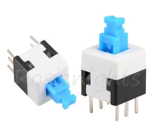 |
| Typical toggle switch - click to buy |
Let's consider the state of a GPIO pin to which either of these is connected. First the tact switch will go from 0 to 1 and then back to 0 again very quickly. Do you want to react to the 0 or the 1? The toggle switch on the other hand will go from 0 to 1 and may well stay that way till you power off your device. Or it may go back from 1 to 0 a few seconds later when you press it again.
Now imagine you only have tact switches, but you want your app to behave as if they were toggle switches.You would need to monitor a 0 to 1 transition and then hold some internal state denoting "on". The next time you get a 0 to 1 transition you would have to remember is was already "on" (in your program's mind) and obviously set your internal state to "off".
Conceptually, we have created a difference between a 1 state and being "on" as well as "0" no longer meaning "off"...enter the Esparto method of "raw" and "cooked".
Raw is simply the current binary value of the pin. Cooked is the on/off state your program needs to know. In the above example, if you tell Esparto your tact switch is a "Latching" switch, it will do all of the above for you, i.e. the raw state will go from 0 to 1, but the cooked state will go to 1, or conceptually "on". When you press and release again, the raw state will (again) go from 0 to 1, but this time Esparto will set the cooked state to 0 or conceptually "off".
Once you have got your head around that, imagine a PIR sensor. Typically they will re-trigger themselves and stay "on" while ever anything big and warm (like a burglar) moves within their field of view. They will stay that way until a certain time has elapsed after the last detected movement. Digitally, we might have something like:
1...0....1........0.....1....................0
where the dots represent the passing of time. The first 1 might be our burglar entering the garden, so on goes the security light - he freezes and the sensor drops back to zero, but the light doesn't go off yet because the gap between the 0 and 1 is too short for the timeout. Then he moves again, for a longer time and then jumps back over the fence. Many dots later the PIR has detected no movement and so turns off.
Esparto has a "Retriggering" type where the raw pattern will be exactly the same, but the cooked value will be:
1.................................................0
Which is to say that you will get told when to turn on the light and when to turn off the light, which - let's face it - is all you wanted to know in the first place. Esparto takes care of resetting the timer on any intervening raw inputs, but only notifies you via the cooked input when something "interesting" happens.
Debouncing
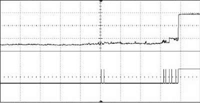
To complicate matters, no switch in reality actually behaves as simply as described above, they "bounce". This means that instead of the tact going 0...1 it might go 01010...1..0......1, bounce back and forth as the springy mechanical contacts settle.(just thing of a carton boi-oi-oi-ongggg! noise). It might look something like this:
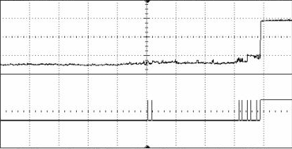
If you hook that switch to a light, it will flash on and off horribly before staying on. The tricky process of making sense of all those ups and downs is called "debouncing". There is much more to it than this, read more here if you are interested, but the good news is: Esparto takes care of all that for you too. No matter how bouncy the raw switch gets, you will get a clean cooked 0..1 every time.
Now we can return to image of the web UI: the top row of LEDs are the raw pin values and the bottom row (with only two LEDs in it, because the demo code only defines two pins) is the cooked value. In between is the mapping between ESP8266 GPIO numbers and Arduino digital pin numbers - very handy to make sure your wiring is correct!
The LEDs flicker as close as possible to the real-time status of the pin so you can actually see what your code is doing.
In part 2 and onwards, we will look at the lower panels and the wide range of facilities that Esparto provides.
Wednesday, 8 August 2018
ESP8266 music-driven flasher in only 6 lines of code!!! (Part 1)
Firstly, I must apologise for having been away so long - I had a little medical problem. (Well, not so little...). What is little though is the number of lines you need to get a fully functional and stable ESP8266 / Arduino project off the ground using my "Esparto" library (of which more later)
Let's see it working. Second apology: I'm sorry about the distracting voiceover on the video but I discovered that Facebook recognises audio content and mutes them if it detecs copyrighted content! It's both unnerving and clever. Since I chose David Bowie's "China Girl" for the demo, I fell foul of the rule, of which - up until that point - I was blissfully unaware! I broke the system by talking loudly over it and re-uploading.
Now I guess that flashing LEDs on ESP8266s are not a new thing, but the whole point of the demo is this, which I hope is more surprising:
There's not much to explain, the pinMode does what the standard Arduino pinMode does, and a little bit more. The two extra parameters tell Esparto when the pin is "active" i.e. what binary state constitues "on" and what its inital state should be, thus saving you the digitalWrite. It defaults to LED_BUILTIN and on many dev boards it is active LOW, i.e. when you write 0 its turns on and goes off when you write 1. So here, we tell it to start "off" which is HIGH for the LED_BUILTIN on a Wemos D1, If that's confusing, I agree, but Esparto worries about all that for you. The Esparto.pinMode defaults are ...,HIGH, LOW); for "normal" LEDs so if yours is one of those just write: Esparto.pinMode(MY_LED,OUTPUT); as you would do normally, where MY_LED is set to your chosen active HIGH "normal" pin.
The next line is where the action happens - all of it. The syntax may look a) new b) odd c) horrible, and if you don't know what a C++ "lambda function is, look it up now. A good explanation can be found here. You don't need one for Esparto, the name of an ordinary function will do e.g. onPinChange - but using the lambda saves you having to write a whole extra function whose core is juist one line - in this case pulseLED.
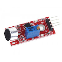
Esparto's pulseLED does exactly what it says on the tin: it pulses or "blips" an output pin for a given number of milliseconds. In our case we choose just one millisecond which may seem as if its going to be waaay to short for our eyes to see. The sound sensor - when calibrated correctly - is going to be throwing binary 1s and 0s into pin D6 faster than you can dream of so when you "stack up" a lot of 1ms pulse into a second you get...well, you have seen the video!
So this weird "lambda" thing just calls pulseLED and because we have used the "raw" version of Esparto's many input pin types, we will get every* flicker. The pin value is passed to the lambda (or your own function) every time it changes* in the v parameter. So we filter out only the 1s (a bit like a RISING interrupt - if you know what that is - and a forthcoming blogpost will explain why with Esparto, 99% of the time you don't need to).
If it makes you feel easier, the following does exactly the same:
It's just that the lambda version allows me to make the (much more) astounding claim of "...in only 6 lines"! Well worth the effort, I thought.
And that's all there is to it. If you are not impressed, then think of this:
If you change the Esparto line to: ESPArto Esparto(yourSSID.yourPWD); a number of wonderful things occur.
Firstly, you will be abe to see a webserver running on your tiny device that allows you to watch the pins flash on and off, reconfigure itself in numerous ways and even simulate receiving MQTT commands...Oh, I almsot forgot: it responds to Amazon's Alexa.
If that sounds all a little too flashy(1) then be aware you can also flash any LED with just 1 line: flashLED(1000,myPin) for example. Or flash a series of pulses in PWM style, e.g. flashLED(1000,25, myPin) will give a 250ms pulse (25% of 1000) every 1sec (1000ms). Enough? What about flashing a repetetive pattern such as S-O-S in morse code? Yes, you guessed it: flashLED("... --- ...",myPin). You can even have many LEDs all flashing at different rates, patterns etc without any problems and with only a few lines of code.
If a raw pin is no use to you, choose from:
*as long as it happens no less than 120 microseconds after the previous one...a forthcoming article will explain this and why using notoriously tricky interrupts may well be a thing of the past since Esparto
Let's see it working. Second apology: I'm sorry about the distracting voiceover on the video but I discovered that Facebook recognises audio content and mutes them if it detecs copyrighted content! It's both unnerving and clever. Since I chose David Bowie's "China Girl" for the demo, I fell foul of the rule, of which - up until that point - I was blissfully unaware! I broke the system by talking loudly over it and re-uploading.
Now I guess that flashing LEDs on ESP8266s are not a new thing, but the whole point of the demo is this, which I hope is more surprising:
#include <ESPArto.h>

ESPArto Esparto;

void setupHardware(){

    Esparto.Output(LED_BUILTIN,LOW,HIGH);

    Esparto.Raw(D6,INPUT_PULLUP,[](int v){ if(v) Esparto.pulseLED(1); });

}
No, there is nothing missing: that's the whole code! And it "just works" as you can see from the video. Yes, there is no setup() function and no loop() function. Esparto takes care of all of that. It manages the whole of the ESP8266 hardware (with all its complexities and traps waiting for the unwary beginner) and calls your code only when it is safe to do so. This means no more random crashes, WDT resets and other common "gotcha"s.There's not much to explain, the pinMode does what the standard Arduino pinMode does, and a little bit more. The two extra parameters tell Esparto when the pin is "active" i.e. what binary state constitues "on" and what its inital state should be, thus saving you the digitalWrite. It defaults to LED_BUILTIN and on many dev boards it is active LOW, i.e. when you write 0 its turns on and goes off when you write 1. So here, we tell it to start "off" which is HIGH for the LED_BUILTIN on a Wemos D1, If that's confusing, I agree, but Esparto worries about all that for you. The Esparto.pinMode defaults are ...,HIGH, LOW); for "normal" LEDs so if yours is one of those just write: Esparto.pinMode(MY_LED,OUTPUT); as you would do normally, where MY_LED is set to your chosen active HIGH "normal" pin.
The next line is where the action happens - all of it. The syntax may look a) new b) odd c) horrible, and if you don't know what a C++ "lambda function is, look it up now. A good explanation can be found here. You don't need one for Esparto, the name of an ordinary function will do e.g. onPinChange - but using the lambda saves you having to write a whole extra function whose core is juist one line - in this case pulseLED.
Esparto's pulseLED does exactly what it says on the tin: it pulses or "blips" an output pin for a given number of milliseconds. In our case we choose just one millisecond which may seem as if its going to be waaay to short for our eyes to see. The sound sensor - when calibrated correctly - is going to be throwing binary 1s and 0s into pin D6 faster than you can dream of so when you "stack up" a lot of 1ms pulse into a second you get...well, you have seen the video!
So this weird "lambda" thing just calls pulseLED and because we have used the "raw" version of Esparto's many input pin types, we will get every* flicker. The pin value is passed to the lambda (or your own function) every time it changes* in the v parameter. So we filter out only the 1s (a bit like a RISING interrupt - if you know what that is - and a forthcoming blogpost will explain why with Esparto, 99% of the time you don't need to).
If it makes you feel easier, the following does exactly the same:
...

void onPinChange(int v){

if(v){
  smartPins.pulseLED(1);
  }
}

...

Esparto.Raw(D6,INPUT_PULLUP,onPinChange);
...
It's just that the lambda version allows me to make the (much more) astounding claim of "...in only 6 lines"! Well worth the effort, I thought.
And that's all there is to it. If you are not impressed, then think of this:
If you change the Esparto line to: ESPArto Esparto(yourSSID.yourPWD); a number of wonderful things occur.
Firstly, you will be abe to see a webserver running on your tiny device that allows you to watch the pins flash on and off, reconfigure itself in numerous ways and even simulate receiving MQTT commands...Oh, I almsot forgot: it responds to Amazon's Alexa.
If that sounds all a little too flashy(1) then be aware you can also flash any LED with just 1 line: flashLED(1000,myPin) for example. Or flash a series of pulses in PWM style, e.g. flashLED(1000,25, myPin) will give a 250ms pulse (25% of 1000) every 1sec (1000ms). Enough? What about flashing a repetetive pattern such as S-O-S in morse code? Yes, you guessed it: flashLED("... --- ...",myPin). You can even have many LEDs all flashing at different rates, patterns etc without any problems and with only a few lines of code.
If a raw pin is no use to you, choose from:
- Debounced
- Encoder
- EncoderAuto
- Latching
- Polled
- Reporting
- Retriggering
- Timed
One important point to note is to power it from the 3.3v rail. NOT the 5v! Connect the lead labelled DO (Digital Output) to your chosen pin on your ESP8266, nodeMCU etc - Esparto works on pretty much any dev board with an ESP-12 module on it. The demo uses a Wemos (now LOLIN) D1 mini and I chose GPIO12 which is Arduino digital D6 and turn the music up LOUD! Seriously, those cheap sensors are not very sensitive and you will need to be very close to the speaker. Also, you will have to calibrate the sensor by twiddling the tiny trimpot until it is just on the edge of going wild...then sit back and enjoy.
In part 2, we will look at a slightly more advanced version that a) uses a different technique from Esparto's built-in pulseLED function and b) uses a rotary encoder to "tweak" the LED response for a much more subtle and pleasing effect. Don't worry, as you may expect by now, its only a few extra lines.
*as long as it happens no less than 120 microseconds after the previous one...a forthcoming article will explain this and why using notoriously tricky interrupts may well be a thing of the past since Esparto
Friday, 10 November 2017
Automatic unattended update of ESP8266 firmware using http server
One of the design goals for my home automation system was to be able to performs OTA (over-the-air) updates. The Arduino IDE makes this very easy, but when you have many devices deployed, it becomes a trifle tedious.
An easier way is to run and "update server" on your network and have each device check at boot time (or via an MQTT message) whether a newer version exists and if so, update itself automatically.
The central issue then is building the update server. The server software, language etc are unimportant: it's the logic of how it responds to the request that matters. The excellent ESP8266httpUpdate class makes it very simple.
My own server is a "flow" in my NODE-RED controller on a raspberry Pi and - as you will see shortly - the logic is actually very simple.
What makes this all possible is the extra "headers" that the ESP8266HTTPUpdate class adds to the outgoing http request. They allow a great deal of control (should you need it) over how each device is updated.
x-ESP8266-STA-MAC
x-ESP8266-AP-MAC
x-ESP8266-free-space
x-ESP8266-sketch-size
x-ESP8266-sketch-md5
x-ESP8266-chip-size
x-ESP8266-sdk-version
x-ESP8266-mode set to either "spiffs" or "sketch"
x-ESP8266-version
This information allows the server to check that the upload will fit into the requesting device's memory, or provide a specific binary for a specific chip using the unique MAC address. Note also that you can also update a SPIFFS image (e.g. you inbuilt web pages / images scripts etc). The most important item is the version. This can be anything you decide.
The simple protocol and logic is this:
Device: "Hi, I'm firmware version a.b.c, do you have a newer version?"
Server: "Let me see...ah yes I have a.b.d - here it comes..."
If a newer version does exists the server just sends it as a load of binary data in the http reply. The ESP8266httpUpdate class does the tricky part of copying the binary into memory, changing the firmware boot address to the new code than (if requested) rebooting the device to run the new coded
If on the other hand there is no higher version, it replies with a http 304 error which effectively says: "I have nothing for you" and your code continues to run as normal.
Here's my NODE-RED update flow which shows the simplicity of it:
 The salmon pink "nodes" are functions written in javascript - before delving into the actual code (which is minimal) we need to talk a little more about my setup:
On my server, I have a folder called /home/pi/trucFirmware which contains:
-rw-r--r-- 1 pi pi 65536 Nov 7 10:22 spiffs_0_4_3_1M.bin
-rw-r--r-- 1 pi pi 1028096 Nov 7 10:22 spiffs_0_4_3_4M.bin
-rw-r--r-- 1 pi pi 352192 Oct 17 13:37 truc_0_4_0.ino.d1_mini.bin
-rw-r--r-- 1 pi pi 344336 Oct 17 13:34 truc_0_4_0.ino.esp01s.bin
-rw-r--r-- 1 pi pi 352208 Oct 17 13:39 truc_0_4_0.ino.nodemcu.bin
-rw-r--r-- 1 pi pi 344528 Oct 17 13:35 truc_0_4_0.ino.sonoff_basic.bin
-rw-r--r-- 1 pi pi 347552 Oct 17 13:36 truc_0_4_0.ino.sonoff_sv.bin
-rw-r--r-- 1 pi pi 348144 Nov 9 17:46 truc_0_4_3.ino.sonoff_basic.bin
I maintain a separate binary for each hardware type (from a single source file with a few #defines) and when a new release is ready I use the Arduino IDE "sketch/Export compiled Binary" menu command for each target device.
Note that even though there are 5 different hardware types, there are only two SPIFFS binaries: a 1M and a 4M version - constructed with the mkspiffs tool - since all the devices have either 1M or 4M flash.
Once you have the mkspiffs tool, building the spiffs is simple. I have a one-line batch file for the 1M version which takes the version number as a parameter (%1)
mkspiffs -c data/ spiffs_%1_1M.bin
and another for the 4M version:
mkspiffs -p 256 -b 8192 -s 0x0FB000 -c data/ spiffs_%1_4M.bin
I then copy all the compile binaries and the SPIFFS .bin files over to /home/pi/trucFirmware
The whole process then, goes like this:
The sketch contains the following code:
When I'm ready, I call _actualUpdate(true); and the action then moves to the server:
The first node in the diagram above "listens" for an http request to url http://192.168.1.4:1880/update with the device type appended. It passes this to "Construct search path" function node which has the following javascript code:
This just sets up the appropriate path with wildcard for the sys function which follows, which simply runs ls - r <msg.payload>
The output is then fed to the "Compare versions" function node:
There you have it: automatic unattended updates. All you need to do is copy the new binaries to your sever and - voila! - the rest "just happens". It certainly makes my life easier with 8x ESP-01S, 6x Wemos D1, 4x Sonoff Basic 10x Sonoff S20, 2x Sonoff SV and a NodeMCU - 31 devices in all to update when I make a code change.
Doing is this way is almost effortless.
An easier way is to run and "update server" on your network and have each device check at boot time (or via an MQTT message) whether a newer version exists and if so, update itself automatically.
The central issue then is building the update server. The server software, language etc are unimportant: it's the logic of how it responds to the request that matters. The excellent ESP8266httpUpdate class makes it very simple.
My own server is a "flow" in my NODE-RED controller on a raspberry Pi and - as you will see shortly - the logic is actually very simple.
What makes this all possible is the extra "headers" that the ESP8266HTTPUpdate class adds to the outgoing http request. They allow a great deal of control (should you need it) over how each device is updated.
x-ESP8266-STA-MAC
x-ESP8266-AP-MAC
x-ESP8266-free-space
x-ESP8266-sketch-size
x-ESP8266-sketch-md5
x-ESP8266-chip-size
x-ESP8266-sdk-version
x-ESP8266-mode set to either "spiffs" or "sketch"
x-ESP8266-version
This information allows the server to check that the upload will fit into the requesting device's memory, or provide a specific binary for a specific chip using the unique MAC address. Note also that you can also update a SPIFFS image (e.g. you inbuilt web pages / images scripts etc). The most important item is the version. This can be anything you decide.
The simple protocol and logic is this:
Device: "Hi, I'm firmware version a.b.c, do you have a newer version?"
Server: "Let me see...ah yes I have a.b.d - here it comes..."
If a newer version does exists the server just sends it as a load of binary data in the http reply. The ESP8266httpUpdate class does the tricky part of copying the binary into memory, changing the firmware boot address to the new code than (if requested) rebooting the device to run the new coded
If on the other hand there is no higher version, it replies with a http 304 error which effectively says: "I have nothing for you" and your code continues to run as normal.
Here's my NODE-RED update flow which shows the simplicity of it:
On my server, I have a folder called /home/pi/trucFirmware which contains:
-rw-r--r-- 1 pi pi 65536 Nov 7 10:22 spiffs_0_4_3_1M.bin
-rw-r--r-- 1 pi pi 1028096 Nov 7 10:22 spiffs_0_4_3_4M.bin
-rw-r--r-- 1 pi pi 352192 Oct 17 13:37 truc_0_4_0.ino.d1_mini.bin
-rw-r--r-- 1 pi pi 344336 Oct 17 13:34 truc_0_4_0.ino.esp01s.bin
-rw-r--r-- 1 pi pi 352208 Oct 17 13:39 truc_0_4_0.ino.nodemcu.bin
-rw-r--r-- 1 pi pi 344528 Oct 17 13:35 truc_0_4_0.ino.sonoff_basic.bin
-rw-r--r-- 1 pi pi 347552 Oct 17 13:36 truc_0_4_0.ino.sonoff_sv.bin
-rw-r--r-- 1 pi pi 348144 Nov 9 17:46 truc_0_4_3.ino.sonoff_basic.bin
I maintain a separate binary for each hardware type (from a single source file with a few #defines) and when a new release is ready I use the Arduino IDE "sketch/Export compiled Binary" menu command for each target device.
Note that even though there are 5 different hardware types, there are only two SPIFFS binaries: a 1M and a 4M version - constructed with the mkspiffs tool - since all the devices have either 1M or 4M flash.
Once you have the mkspiffs tool, building the spiffs is simple. I have a one-line batch file for the 1M version which takes the version number as a parameter (%1)
mkspiffs -c data/ spiffs_%1_1M.bin
and another for the 4M version:
mkspiffs -p 256 -b 8192 -s 0x0FB000 -c data/ spiffs_%1_4M.bin
I then copy all the compile binaries and the SPIFFS .bin files over to /home/pi/trucFirmware
The whole process then, goes like this:
The sketch contains the following code:
#include<esp8266httpupdate.h>
...
#define TRUC_VERSION "0_4_99"
// THIS_DEVICE is set earlier depending on various compile-time defines
// which eventually define the hw type, e.g. #define THIS_DEVICE "d1_mini"
const char * updateUrl="http://192.168.1.4:1880/update/"THIS_DEVICE;
// this is my raspberry Pi server, the 1880 is the default NODE-RED port
// /update is the url I chose for the server to "listen" for, followed by the device type
...
bool ICACHE_FLASH_ATTR  _actualUpdate(bool sketch=false){
    String msg;
    t_httpUpdate_return ret;

    ESPhttpUpdate.rebootOnUpdate(false);
    if(sketch){
      msg="sketch";
      ret=ESPhttpUpdate.update(updateUrl,TRUC_VERSION);     // **************** This is the line that "does the business"
    }
    else {
      msg="SPIFFS";
      ret=ESPhttpUpdate.updateSpiffs(updateUrl,CSTR(E.getSPIFFSVersion()));
    }
    if(ret!=HTTP_UPDATE_NO_UPDATES){
      if(ret==HTTP_UPDATE_OK){
        msg.concat(" upgraded");
        Esparto.publish("update",CSTR(msg));
        return true;
        }
      else {
        if(ret==HTTP_UPDATE_FAILED){
          msg.concat(" upgrade FAILED code:");
          msg.concat(ESPhttpUpdate.getLastError());
          msg.concat(" reason:");
          msg.concat(CSTR(ESPhttpUpdate.getLastErrorString()));
          Esparto.publish("update",CSTR(msg));
          }
        }
      }
  return false;
}
When I'm ready, I call _actualUpdate(true); and the action then moves to the server:
The first node in the diagram above "listens" for an http request to url http://192.168.1.4:1880/update with the device type appended. It passes this to "Construct search path" function node which has the following javascript code:
msg.type=msg.req.params.type;
var h=msg.req.headers;
msg.version=h["x-esp8266-version"];

msg.mode=h["x-esp8266-mode"];
if(msg.mode=="sketch"){
    msg.payload="/home/pi/trucFirmware/*.ino."+msg.type+".bin";
}
else {
    var sz=h['x-esp8266-chip-size'];
    msg.payload="/home/pi/trucFirmware/spiffs_*_"+(sz/1048576)+"M.bin";
}
return msg;
This just sets up the appropriate path with wildcard for the sys function which follows, which simply runs ls - r <msg.payload>
The output is then fed to the "Compare versions" function node:
var f=msg.payload.split("\n")[0];
msg.filename=f;

if(msg.mode=="sketch"){
    f=f.replace("/home/pi/trucFirmware/truc_","");
    f=f.replace(".ino."+msg.type+".bin","");
}
else {
    f=f.replace("/home/pi/trucFirmware/spiffs_","");
    f=f.replace(/_\dM\.bin/,"");
}

if(msg.version<f){
    node.warn("upgrade required");
    node.warn("will return "+msg.filename);
    return msg;
}
node.warn("no upgrade");
msg.statusCode=304;
msg.payload=[];

return msg;
The switch node then ensures that either the 304 "no update needed" message is sent or the actual new binary is returned and sent back to the device.There you have it: automatic unattended updates. All you need to do is copy the new binaries to your sever and - voila! - the rest "just happens". It certainly makes my life easier with 8x ESP-01S, 6x Wemos D1, 4x Sonoff Basic 10x Sonoff S20, 2x Sonoff SV and a NodeMCU - 31 devices in all to update when I make a code change.
Doing is this way is almost effortless.
Wednesday, 1 November 2017
Esparto v2.0 - sneak preview: Inside
"A picture is worth..." as they say:
The following 21 lines (one of which is a comment...) are all you need to turn a Sonoff Basic, S20 or SV into an MQTT device with a web interface...etc etc as described in the previous post "...outside". If you don't want diagnostics, you can lose the Serial,begin and cut another line.
The Sonoffs have a push button on GPIO0 and a mains relay on GPIO12. That's all they have, hardware-wise
And the code above is all they need, and I ask you: "What could be simpler?"
True, you will have to physically FLASH upgrade it first time with a FTDI adapter, but after that, Esparto will update itself automatically as needed. It will appear on your WiFi network as esparto666.local and respond to an MQTT "switch" command, by toggling the power relay and will reply with an MQTT "state" message with a payload of "ON" or OFF". It will reconnect after any network failure and all the while, the manual button will still turn it on an off.
Plus it's inside your own network. No snazzy (but often rubbish) App to download. No security problems. No worrying if XYZ corp go out of business and close their cloud, that your lights will never work again...If you can use a web browser, you can control it. If you have an MQTT server, you can control it in much more detail. If you have a NODE-RED server, you can start to do really clever things with your whole house.
Let's look inti the code in more detail (shouldn't take long)
It doesn't look much like a typical Arduino sketch. There is no setup() function and no loop function. Esparto takes care of both, to make sure things are done in the "right" order and to prevent your code from accidentally breaking things or stopping it working.
Your code is all driven asynchronously by Esparto using callbacks. If you don't know what that means, you need to read the sidebar articles under "Essential Information". It starts with setupHardware. This is where you do what you'd normally do in setup. Having said that, much of what you'd "normally do" isn't needed any more.
Tells Esparto that you want the button on GPIO0 debounced (for 15ms) and to call buttonPressed when someone pushes it or lets it go - i.e. when it changes. When it goes HIGH (the button on a Sonoff is "reversed" in sense: it goes LOW when you press it and HIGH when released) the relay is set to the opposite of what it is now. If its already on, it goes off etc - and that is the same as the standard firmware that it comes with when you buy it.
When Esparto has established a valid MQTT connection it calls onMqttConnect. Here, your code tells Esparto you want to receive "switch" topic message and when it gets one, it will call your code in mqttSwitch. As for a button press, you call toggleRelay which then publishes the current switch state to MQTT.
"And that's that"...as they also say.
Adding sensors to a "homebrew" board and adding lots of functionality on top of this is going to get more complex of course, but Esparto is designed to take a lot of the hard work out of that process too. It has a lot of "Hooks" where you can add callbacks in exactly the places you need to create a new "layer" of your own HA system on top of Esparto. That's how my own Chez Toi ioT system works: 90% of the code in each device is Esparto. Esparto has 9 different types of input pin it can manage for you, including rotary encoders and each of those only require one or two lines of code.
As an example my truc firmware when I fisrt wrote it was about 1200 lines of (pretty hairy) code and a lot of bugs. Now it handles GPIO on every pin of a WemosD1 and runs temperature PIR, sound, light, button and touch sensors. It also controls 433MHz RF switches, and it auto-updates itself. It's far more robust, easier to control and has two web pages (one of which is a live GPIO view) when the old one had only one very basic config page. Using Esparto, its only about 300 lines long and most of those 300 lines are a lot simpler and a lot more obvious to read.
But the biggest "gift" it brings is this: it runs all your code on the main loop thread, in a non-overlapping "job queue". All asynchronous events are "serialised" into the queue so no more problems of resource clashes, hangups, WDT resets and a hundred other headaches. It also provides tools for you to do the same from your own code. Each task runs separately in turn and can't interfere with/break/stop any other task, unless you deliberately make it do so. Again, if you don't know what all that means, read the "Essential Information" but what it translates to is: It prevents you from accidentally falling into about 90% of the common traps that newcomers fall into - and not all of them are obvious even to some experts. Some of them confuse experienced programmers for days and make grown men weep. Kiss 'em all goodbye.
It's fair to say that some of the complexity that Esparto hides (by deliberate design) would easily put off a lot of beginners, so having "MQTT in a box" is a huge help to getting started in the world of Home Automation and IOT. Now its absolutely true that if you can write a simple sketch to flash an LED you can also write one to produce your own Sonoff firmware. How's that sound for starters?
Of course Sonoff aren't the only player in town: that exact same sketch above will compile and run on Wemos D1, NodeMCU and (with a touch of "fettling" and shifting pin 12 to e.g. GPIO2) even an ESP-01 or ESP-01S.
Esparto is the result of 2years' worth of thousands of mistakes, false starts, burned fingers, frustration and swearing - so that you don't have to go through it all again yourself.
The following 21 lines (one of which is a comment...) are all you need to turn a Sonoff Basic, S20 or SV into an MQTT device with a web interface...etc etc as described in the previous post "...outside". If you don't want diagnostics, you can lose the Serial,begin and cut another line.
The Sonoffs have a push button on GPIO0 and a mains relay on GPIO12. That's all they have, hardware-wise
#include <ESPArto.h>
// ToiioT-Etage is my SSID, pw="" (I live in the forest) my raspi mosquitto is on 192.168.1.4
ESPArto Esparto("ToiioT-Etage", "", "esparto666", "192.168.1.4", 1883);
void buttonPressed(bool hilo){
  if(hilo) toggleRelay();
}
void mqttSwitch(String topic,String payload){
  toggleRelay();
  Esparto.publish("state",digitalRead(12) ? "ON":"OFF");
}

void setupHardware(){
   Serial.begin(74880);
   Esparto.Debounced(0,INPUT,15,buttonPressed); // 15 = ms debounce time
   pinMode(12,OUTPUT); // relay / switch
}
void onMqttConnect(){
  Esparto.subscribe("switch",mqttSwitch);
}
void toggleRelay(){
  digitalWrite(12,!digitalRead(12));
}
And the code above is all they need, and I ask you: "What could be simpler?"
True, you will have to physically FLASH upgrade it first time with a FTDI adapter, but after that, Esparto will update itself automatically as needed. It will appear on your WiFi network as esparto666.local and respond to an MQTT "switch" command, by toggling the power relay and will reply with an MQTT "state" message with a payload of "ON" or OFF". It will reconnect after any network failure and all the while, the manual button will still turn it on an off.
Plus it's inside your own network. No snazzy (but often rubbish) App to download. No security problems. No worrying if XYZ corp go out of business and close their cloud, that your lights will never work again...If you can use a web browser, you can control it. If you have an MQTT server, you can control it in much more detail. If you have a NODE-RED server, you can start to do really clever things with your whole house.
Let's look inti the code in more detail (shouldn't take long)
It doesn't look much like a typical Arduino sketch. There is no setup() function and no loop function. Esparto takes care of both, to make sure things are done in the "right" order and to prevent your code from accidentally breaking things or stopping it working.
Your code is all driven asynchronously by Esparto using callbacks. If you don't know what that means, you need to read the sidebar articles under "Essential Information". It starts with setupHardware. This is where you do what you'd normally do in setup. Having said that, much of what you'd "normally do" isn't needed any more.
Esparto.Debounced(0,INPUT,15,buttonPressed);
Tells Esparto that you want the button on GPIO0 debounced (for 15ms) and to call buttonPressed when someone pushes it or lets it go - i.e. when it changes. When it goes HIGH (the button on a Sonoff is "reversed" in sense: it goes LOW when you press it and HIGH when released) the relay is set to the opposite of what it is now. If its already on, it goes off etc - and that is the same as the standard firmware that it comes with when you buy it.
When Esparto has established a valid MQTT connection it calls onMqttConnect. Here, your code tells Esparto you want to receive "switch" topic message and when it gets one, it will call your code in mqttSwitch. As for a button press, you call toggleRelay which then publishes the current switch state to MQTT.
"And that's that"...as they also say.
Adding sensors to a "homebrew" board and adding lots of functionality on top of this is going to get more complex of course, but Esparto is designed to take a lot of the hard work out of that process too. It has a lot of "Hooks" where you can add callbacks in exactly the places you need to create a new "layer" of your own HA system on top of Esparto. That's how my own Chez Toi ioT system works: 90% of the code in each device is Esparto. Esparto has 9 different types of input pin it can manage for you, including rotary encoders and each of those only require one or two lines of code.
As an example my truc firmware when I fisrt wrote it was about 1200 lines of (pretty hairy) code and a lot of bugs. Now it handles GPIO on every pin of a WemosD1 and runs temperature PIR, sound, light, button and touch sensors. It also controls 433MHz RF switches, and it auto-updates itself. It's far more robust, easier to control and has two web pages (one of which is a live GPIO view) when the old one had only one very basic config page. Using Esparto, its only about 300 lines long and most of those 300 lines are a lot simpler and a lot more obvious to read.
But the biggest "gift" it brings is this: it runs all your code on the main loop thread, in a non-overlapping "job queue". All asynchronous events are "serialised" into the queue so no more problems of resource clashes, hangups, WDT resets and a hundred other headaches. It also provides tools for you to do the same from your own code. Each task runs separately in turn and can't interfere with/break/stop any other task, unless you deliberately make it do so. Again, if you don't know what all that means, read the "Essential Information" but what it translates to is: It prevents you from accidentally falling into about 90% of the common traps that newcomers fall into - and not all of them are obvious even to some experts. Some of them confuse experienced programmers for days and make grown men weep. Kiss 'em all goodbye.
It's fair to say that some of the complexity that Esparto hides (by deliberate design) would easily put off a lot of beginners, so having "MQTT in a box" is a huge help to getting started in the world of Home Automation and IOT. Now its absolutely true that if you can write a simple sketch to flash an LED you can also write one to produce your own Sonoff firmware. How's that sound for starters?
Of course Sonoff aren't the only player in town: that exact same sketch above will compile and run on Wemos D1, NodeMCU and (with a touch of "fettling" and shifting pin 12 to e.g. GPIO2) even an ESP-01 or ESP-01S.
Esparto is the result of 2years' worth of thousands of mistakes, false starts, burned fingers, frustration and swearing - so that you don't have to go through it all again yourself.
Esparto v2.0 - sneak preview: Outside
"Esparto" is a type of coarse grass. That's neither here nor there really but it's a nice name for this Arduino ESP8266 library. Originally it stood for ESP All-purpose Run-Time Object, but it could just as well be "ESP All Ready To Operate" because that's what it is.
It is a C++ class object which does almost everything you need to do to turn your Wemos D1, NodeMCU, ESP-01S or Sonoff device from a pretty brick into an MQTT-controlled IOT device. Some folk would call it "firmware" and indeed you can upload a binary if you choose, but the real power comes when you extend it yourself with your own code.
As it stands, it will connect to your WiFi and MQTT controller and automatically reconnect after they fail - without rebooting. It will give you a visual (near*) real-time view of all the GPIO pins, with the correct labels on each depending on the device its deployed on. It will accept OTA updates and runs a web server that allows simple reconfiguration.
Using MQTT you can switch it on of off, reboot it (though you shouldn't need to) or factory-reset it. You can even dynamically change its deviceID and SSID+Password. You can read or write any IO pin and/or reconfigure them. What that last one means exactly will become clear later. Through all of this the basic on/off functionality will continue to work, even if your MQTT controller or complete local network are down.You don't need someone else's cloud and a flaky app on your iPhone. Anything that runs a web browser inside your network can control it. So even without your own additional code, it already does a lot.
Once you start adding your own code, the world of Home Automation and IOT is your oyster. In the example that follows, the device is running mu own Chez Toi ioT "truc" firmware, which provides a common interface for a number of sensors (PIR, light, sound, temperature) adds RF433MHz "dumb" switch control and stores the location and function of the device so that the NODE-RED controller can present a smooth UI for the overall management of the whole system.
Basic Esparto:


It is a C++ class object which does almost everything you need to do to turn your Wemos D1, NodeMCU, ESP-01S or Sonoff device from a pretty brick into an MQTT-controlled IOT device. Some folk would call it "firmware" and indeed you can upload a binary if you choose, but the real power comes when you extend it yourself with your own code.
As it stands, it will connect to your WiFi and MQTT controller and automatically reconnect after they fail - without rebooting. It will give you a visual (near*) real-time view of all the GPIO pins, with the correct labels on each depending on the device its deployed on. It will accept OTA updates and runs a web server that allows simple reconfiguration.
Using MQTT you can switch it on of off, reboot it (though you shouldn't need to) or factory-reset it. You can even dynamically change its deviceID and SSID+Password. You can read or write any IO pin and/or reconfigure them. What that last one means exactly will become clear later. Through all of this the basic on/off functionality will continue to work, even if your MQTT controller or complete local network are down.You don't need someone else's cloud and a flaky app on your iPhone. Anything that runs a web browser inside your network can control it. So even without your own additional code, it already does a lot.
Once you start adding your own code, the world of Home Automation and IOT is your oyster. In the example that follows, the device is running mu own Chez Toi ioT "truc" firmware, which provides a common interface for a number of sensors (PIR, light, sound, temperature) adds RF433MHz "dumb" switch control and stores the location and function of the device so that the NODE-RED controller can present a smooth UI for the overall management of the whole system.
Basic Esparto:
From the top: Device name, SSID+password change. No reboot, it just reconnects to the new settings. You will need to browse to another "devicename.local" page of course if you change the name or another IP page if the new SSID has a different range.
We'll come back to the "settings" cog icon in a moment, but the yellow circular arrow reboots the device and the factory icon resets it to as close to its original state as possible.
The next panel shows the current state of all the GPIOs, each labelled appropriately for the type of hardware its running on. The top row is the "raw" state of the pin, i.e. its instantaneous value, irrespective of what is connected to it. If it is configured as an output (e.g. the LED or RELAY in a Sonoff device) clicking the top row pin will toggle the state and switch the GPIO on or off. The bottom row will make more sense in the next article when we look "inside" at the code, but for now, just know that these are what Esparto calls the "cooked" state.
Esparto is based on the SmartPins library, which is itself based on the H4 timer / scheduler library. (See the side panel links to these for full documentation - all the functionality will be available in Esparto V2.0, plus a lot more of course. Or see http://github.com/philbowles/smartpins and http://github.com/philbowles/h4) . I'll also cover in the next post why those are both "good things" and will save you months of pain. SmartPins defines number of useful input types such as "debounced", "latching", "encoder" and several more. It does all the work to manage the pin, keep those lights updated and call your code back when the pin changes. So a "raw" button which is bouncy will flicker on and off as it bounces, but once SmartPins has done all the hard work and debounced the pin it puts the corresponding bottom line "cooked" pin on and calls your code.
The next panel shows some vaguely-useful static information and the final panel shows dynamic information - including MQTT connection status - which is useful when you start adding your own code.
Back to the "setting" gear wheel. Out-of-the-box it will give you a "404" error. That is because it links to a "config" page that you add for the extra functionality that your code provides. Esparto has been specifically designed to make this easy for you, and we'll see just how much so in the next article. For the moment let's look at what Chez Toi ioT "truc" firmware adds:
Chez Toi needs to know where each device lives, to "wire together" important sequences, e.g. "Going to bed" turns on the bedroom light and the landing light and maybe later, the heater if the temperature is below 14degrees. Much of that added "intelligence" is in the raspberry Pi NODE-RED controller in order to keep the code "footprint" in each device as small as possible.
By knowing the location and function, I can add MQTT commands to turn on all devices in a zone, or all floor lamps in the whole system. "Restart" determines if the device is on , off or whatever it was before in the (rare) case of reboot or power outage. A safety nightlight for example would be (as before) but generally "off" is safest.
The numbers (all in milliseconds) are the configuration values for the sensors. PIR(t) is the PIR timeout and PIR(h) is its "hysteresis", meaning the "dead time" between two movement events to prevent it flicking on and off too rapidly. Sound is the timeout value for the re-triggering sound sensor, and light and temp are the frequency to poll those two sensors, since they change slowly.
This particular "truc" is also an RF master controller. When it switches on, those three 433MHz switches will also go on. Or off, of course. Clicking on any will toggle its current state to allow degree of "manual" control. No more searching for the handset - any browser-capable device will do, tablet, phone, PC etc.
Beware of the (watch)dog!
Your house is full of smoke. The smoke alarm is beeping. Do you a) Turn of the smoke alarm and burn alive or b) find the source of the smoke and put out the fire?
I'm sure most folk would opt for b) but the most common problem I see when helping newbies in various esp8266 forums is the programmming equivalent of a). For reasons that are explained elsewhere on this blog LINK programming the ESP8266 isn't the same as programming a "simple" AVR / Arduino etc and part of that difference frequently causes a "watchdog" timer reset - essentially a "crash" followed by a reboot.
These things generally only happen when the programmer doesn't fully grasp all the issues mentioned in the above LINK, but their first attempts to "fix the problem" usually involves "shooting the meesenger" and turning off the smoke alarm...
If you already know what a WDT is, how it works and why, then you will probably disagree with some aspects of my next statement...in which case, pop off somewhere else and let those who don't yet know those answers to allow this to sink in:
DO NOT TOUCH THE WATCHDOG TIMER. YOU DON'T NEED IT. FORGET IT EVEN EXSISTS! WHATEVER YOU THINK THE PROBLEM IS, IT IS ABSOLUTELY NOT THE WATCHDOG TIMER! DON'T FEED IT. DON'T DISABLE IT.
D O N ' T T O U C H I T!!!
The “watchdog” timer (WDT) is the ESP8266’s smoke alarm. It goes off when there is a fundamental problem with your code. You need to find and fix that problem, not mess around with the WDT.
Embedded systems often don’t have the luxury of a screen and/or keyboard and are frequently fitted in difficult-to-access places where they are never seen by the human eye such as behind your living room wall or under the hood of your car - or in my case - 25feet up on a barn roof... When something fatal occurs, they have little option but to automatically reset themselves, thus many such devices have a WDT built into the hardware. This monitors the state of the system and if it freezes, locks / up or loops indefinitely for more than an “acceptable” amount of time, the WDT will reboot the device. After all, an occasionally faulty device is better than no device at all - especially if it controls your brakes.
I see many forum posts where the programmer says one of:
- “I need to understand how the WDT works”
- “There is something wrong with the WDT”
- “My code runs fine on xxxx , but when I run it on the ESP8266, I get a WDT reset”
- “Every time I run my code, I see: WDT reset, please help”.
My answers usually are:
- Oh no you don't (see above)
- Oh no there isn't
- So what?
- Read this blog
It really helps if you have already read the article on "Asynchronous programming". If you haven't, then you need to, because WDT problems are the tip of an iceberg and you need to understand the whole iceberg to get the best out of your ESP8266.
The usual cause of a WDT reset is that your code is “blocking” which means its stopping other processes or "threads" from running. This is often caused by taking too long to do what you think it needs to do. The most common causes I see are indiscriminate use of delay() calls and/or waiting in a loop for an external resource e.g. a remote website.
So how long is “too long” and what is an “acceptable” period of time, when your code already runs fine on an Arduino / stm32 / cray 1 / HP pocket calculator?
ESP8266 is a WiFi capable device – that’s why you bought it, right? Connecting to, disconnecting from, and – more importantly - maintaining a WiFi link os not magic - it takes processing time. There is only one CPU. The most important thing to grasp is that the code you write is not the only code running in the chip. About 200k+ of ESP code is loaded in before you even get to think about blinking an LED. And when does that code run? All the time. It runs “in the background” and you cannot easily see it or find out exactly what it’s doing and when. It just does its thing. Untill you interfere with it and stop it doing its thing. Then the WDT kicks in. It's really quite simple.
If your code stops the WiFi code from running for more than a very short period of time, the WDT says “oops! System has locked up, reboot!”. There is a reason why I have left you thinking "what does 'very short' mean? How long exactly is it?" and the reason is because if you write your programs correctly, you don't need to know. If you really want to, google it.
Yes, you can try to turn off the WDT to “fix” the problem, but like the smoke alarm, it doesn’t remove the source of the fire, it just delays the inevitable. You can turn off the smoke alarm too, but if that is your preferred solution, I won’t be staying at your house, thank you. Even if you turn it off but still don't fix your code, the hardware WDT will probably kick in after a few seconds -and you can't turn that one off, so you are still going to crash - just several seconds later than if you hadn't turned off the software WDT.
Yes, there are ways you can "cheat" and "feed" the watchdog, but all you are doing is putting a blanket over the beeping smoke alarm to obscure the problem and hiding your bad code. Bad code generally finds a way to bite you in the ass no matter what you do, so it's best to find it and get rid of it, don't you think?
The only solution is to find the part of your code which blocks the background processing and then change it so that it doesn't. How to change it is a whole other (complex) story and for that, you definitely need to understand the link you haven't read yet...How do I know you haven't read it? Easy - because if you had, you wouldn't need to be reading this. Now go and read it.
The only way to absolutely guarantee no WDT resets is to write your code so that it can run asynchronously, co-operate fully with other processes and obey all the rules that multitasking requires. Unfortunately, that is a) a whole new way of thinking b) can be quite complex. With some basic rules, you can avoid most of the problems, but don't forget: we are talking about the tip of an iceberg here.
Until you get more experienced and fully understand the above paragraph, try to stick to the following:
1. Never forget that yours is not the only code running.
2. The problem is in your code. Messing with the WDT won’t fix that.
3. Try to avoid delay() if at all possible. Only ever include delay() if it is absolutely needed and you truly understand why it is needed. If both of those aren't true, take it out.
4. Never sit in a loop waiting for an external event to happen. Instead, set a volatile global, test and reset the global in the main loop. The same goes for callbacks and timer events. Or, write your code properly (see above link)
5. Yield() in your main loop.
6. If a library has a “run” or “handle” or “loop” method, always call it, it’s there for a reason! This is usually the way library code does what your code also needs to do: co-operate with all other code running in the CPU. The best place is in your main loop.
7. Never disable the WDT, it’s there for a reason!
Dont' Delay!
The following code looks like it will wait until pin 5 goes LOW until allowing the loop function to run:
T=5204 Waiting
Soft WDT reset
ctx: cont
sp: 3ffef240 end: 3ffef420 offset: 01b0
>>>stack>>>
3ffef3f0: 3fffdad0 00000000 3ffee3c8 40201c28
3ffef400: feefeffe feefeffe 3ffee3ec 4020237c
3ffef410: feefeffe feefeffe 3ffee400 40100718
<<<stack<<<
Now then, this is where it starts to look like a magic trick: Your WiFi SSID and password are not in that sketch and there is of course, nothing up my sleeve - I do not and could not possibly know them. Even if I did, there is no WiFi.begin anywhere in the sketch that would tell the ESP8266 to connect to your WiFi. But it will connect. Go on, if you don't believe me, try it. Surprised? I hope so. Note also that the connection occured after the loop had started running - certainly on my chip it did:
⸮T=6303 Setup
T=6303 LOOP: Do something
T=8126 WiFi got IP 192.168.1.113
T=8126 Connected to LaPique (192.168.1.1) as 192.168.1.113 (ch: 6) hostname=ESP_836EDC
T=36303 LOOP: Do something
What have we learned?
Insert a delay(1) before the Serial.printf in wifiGotIPHandler like so:
Here's what happens on mine:
So now what have we learned?
delay can only be called - without problems - from the "main loop thread". If you call it from the "background thread", you've seen what happens. Some callbacks (especially timers) and all interrupt service routines (ISRs) do not run - by definition - on the main loop thread, so calling delay inside them will cause problems.
We are now in a "catch-22": The best way to write code for the ESP8266 is the event-driven style, but the same method makes other code break. The solution however, is easy: don't use that "other code". Don't use delay. If you need something to happen at a later date, use a Ticker, or the author's H4 library (which adds a lot of functionality to the Ticker class) github.com/philbowles/h4
Many of the ESP8266 libraries use callbacks. If you know - in every case - whether or not it's safe to call delay in the callback, feel free to ignore everything here. But if you don't, don't. Since you can't really do anything much more productive without those libraries other than flashing LEDs, the best starting point is:
Unless, of course you understand all of this already and know exactly what you are doing.
void setup(){

  Serial.begin(74880);

  pinMode(5,INPUT_PULLUP);

  Serial.printf("T=%d Waiting\n",millis());

  while(digitalRead(5)==HIGH);

  Serial.printf("T=%d Ready\n",millis());

}
The while loop is a technique used on other systems - and probably works - but here's what happens on an ESP8266:T=5204 Waiting
Soft WDT reset
ctx: cont
sp: 3ffef240 end: 3ffef420 offset: 01b0
>>>stack>>>
3ffef3f0: 3fffdad0 00000000 3ffee3c8 40201c28
3ffef400: feefeffe feefeffe 3ffee3ec 4020237c
3ffef410: feefeffe feefeffe 3ffee400 40100718
<<<stack<<<
It just crashed. What happened was, your code is in a very tight loop, and while it is there, the WiFi code cannot run. The "watchdog timer" thinks the processor has "hung up" and so it restarts the system. This alone is one good reason is why programming the ESP8266 is different from programming e.g. an AVR with the Arduino IDE. If you replace the while statement with:
while(digitalRead(5)==HIGH) delay(1);
Then it works as you would have expected. The system sits doing nothing until pin 5 goes LOW. So it looks like "delay" is the solution. Before we added it your code was "doing nothing" - and it crashed. It doesn't take a rocket scientist to deduce then that delay cannot also be "doing nothing" therefore it must be doing something!
That something is allowing the WiFi code to run in the background, hence the WDT isn't worried.
Oddly, delay(0) would also have worked. As would the special function yield() which does pretty much the same as delay(0). delay is specifically designed to "yield" the CPU, i.e. "let go" of it for a short while, and in that short while, the WiFi code can use it.
"But Wait!" I hear you cry: "I haven't done anything with WiFi! I haven't even tried to connect to it!" - and that's true. But - look at the crash information: "T=5204" The system had been running for 5.2 seconds before it even got to the while loop. Did Serial.begin and pinMode really take 5 seconds?
If not, then what was the CPU doing for 5 seconds?
To answer that, I'd like to to actually try this experiment: don't just read it and take my word, actually do it. First - and this is vital: if you use a brand new chip or one you have used for "messing about with WiFi" then the following code might not work, You have to use a chip that you have already successfully connected to your WiFi, at least once before. When you have that, load the following sketch:
#include<ESP8266WiFi.h>

#define CSTR(x) x.c_str()
#define TXTIP(x) CSTR(x.toString())

WiFiEventHandler    gotIpEventHandler,disconnectedEventHandler;

void wifiEvent(WiFiEvent_t event) {
    switch(event) {
        case WIFI_EVENT_STAMODE_CONNECTED:
            Serial.printf("T=%d WiFi Connected SSID=%s\n",millis(),CSTR(WiFi.SSID()));
            break;
        case WIFI_EVENT_STAMODE_GOT_IP:
            Serial.printf("T=%d WiFi got IP %s\n",millis(),CSTR(WiFi.localIP().toString()));
            break;
        case WIFI_EVENT_STAMODE_DISCONNECTED:
            Serial.printf("T=%d WiFi lost connection\n",millis());
            break;
        default:
            break;
    }
}

void wifiDisconnectHandler(const WiFiEventStationModeDisconnected& event){
  Serial.printf("T=%d Disconnected (reason=%d)\n",millis(),event.reason);
}

void wifiGotIPHandler(const WiFiEventStationModeGotIP& event){
  Serial.printf("T=%d Connected to %s (%s) as %s (ch: %d) hostname=%s\n",millis(),CSTR(WiFi.SSID()),TXTIP(WiFi.gatewayIP()),TXTIP(WiFi.localIP()),WiFi.channel(),CSTR(WiFi.hostname()));
}

void setup(){
  Serial.begin(74880);
  delay(1000);
  Serial.printf("T=%d Setup\n",millis());
  WiFi.onEvent(wifiEvent);
  gotIpEventHandler = WiFi.onStationModeGotIP(wifiGotIPHandler);
  disconnectedEventHandler = WiFi.onStationModeDisconnected(wifiDisconnectHandler);
  }

void loop(){
  Serial.printf("T=%d LOOP: Do something\n",millis());
  delay(30000);
}
Now then, this is where it starts to look like a magic trick: Your WiFi SSID and password are not in that sketch and there is of course, nothing up my sleeve - I do not and could not possibly know them. Even if I did, there is no WiFi.begin anywhere in the sketch that would tell the ESP8266 to connect to your WiFi. But it will connect. Go on, if you don't believe me, try it. Surprised? I hope so. Note also that the connection occured after the loop had started running - certainly on my chip it did:
⸮T=6303 Setup
T=6303 LOOP: Do something
T=8126 WiFi got IP 192.168.1.113
T=8126 Connected to LaPique (192.168.1.1) as 192.168.1.113 (ch: 6) hostname=ESP_836EDC
T=36303 LOOP: Do something
What have we learned?
- The ESP8266 remembers the last successful WiFi connection and automatically re-connects to it - without you even asking!
- It can take quite a few seconds to connect.
- The ESP8266 is doing a lot of things "in the background" even when you think that nothing else is happening except your code.
Insert a delay(1) before the Serial.printf in wifiGotIPHandler like so:
void wifiGotIPHandler(const WiFiEventStationModeGotIP& event){
  delay(1);
  Serial.printf("T=%d Connected to %s (%s) as %s (ch: %d) hostname=%s\n",millis(),CSTR(WiFi.SSID()),TXTIP(WiFi.gatewayIP()),TXTIP(WiFi.localIP()),WiFi.channel(),CSTR(WiFi.hostname()));
}
Here's what happens on mine:
T=6302 Setup
T=6302 LOOP: Do something
T=8124 WiFi got IP 192.168.1.113
T=8124 Connected to LaPique (192.168.1.1) as 192.168.1.113 (ch: 6) hostname=ESP_836EDC

Exception (9):
epc1=0x401050b9 epc2=0x00000000 epc3=0x00000000 excvaddr=0xffffffff depc=0x00000000

ctx: sys
sp: 3ffffdb0 end: 3fffffb0 offset: 01a0
So now what have we learned?
- That time travel is apparently possible: the delay(1) before the Serial.printf caused the crash (trust me, it did) yet the Serial.printf still worked! Welcome to the wonderful world of asynchronous programming...
- That as little as a 1ms delay can cause a crash? No,we have learned that...
- delay is not - after all - such a wonderful solution: when used in the "wrong" place it is a nightmare.
delay can only be called - without problems - from the "main loop thread". If you call it from the "background thread", you've seen what happens. Some callbacks (especially timers) and all interrupt service routines (ISRs) do not run - by definition - on the main loop thread, so calling delay inside them will cause problems.
We are now in a "catch-22": The best way to write code for the ESP8266 is the event-driven style, but the same method makes other code break. The solution however, is easy: don't use that "other code". Don't use delay. If you need something to happen at a later date, use a Ticker, or the author's H4 library (which adds a lot of functionality to the Ticker class) github.com/philbowles/h4
Many of the ESP8266 libraries use callbacks. If you know - in every case - whether or not it's safe to call delay in the callback, feel free to ignore everything here. But if you don't, don't. Since you can't really do anything much more productive without those libraries other than flashing LEDs, the best starting point is:
D O N O T C A L L D E L A Y
Unless, of course you understand all of this already and know exactly what you are doing.
Event-driven programming with callbacks
The previous article (which you should read now, before you continue) how "callbacks" made programming the ESP8266 easier and less error-prone - but what do they look like and how do they work?
Let's take the case where you want to read a sensor every minute. I've seen a lot of code like this around (or variations of it)
loop() gets called about 40,000 times a second. So you are likely to "do something" up to 40 times because the value of millis() will be the same until another millisecond elapses! So, depending on how long "do something" takes, depends on how often it will be called, which is nothing like what you think you were doing, and if "do something" relies on accurate timing, your program will not work.
"Easy!" you think, "I'll set another global variable while doing something, then check it in loop and make sure I only do something once per loop".
"or, I can put delay(60000) inside the loop and then my timing will be accurate!"
The first option adds more code, more complexity (none of which is necessary and usually frowned upon - for plenty of good reasons - by experienced programmers) and the second just won't work.
No, the solution is to use the Ticker library which runs a highly accurate timer and calls back your code when the timer expires:
The most important thing to realise here is that doSomething does not get called by everyMinute.attach_ms(60000,doSomething) in setup...all you are doing here is telling the Ticker library the name of your function - "registering" it - which will then be called every minute.
In a nutshell, that's how callbacks work. They are lot simpler, a lot cleaner and prevent you from re-inventing the wheel every time you write a sketch. But the most important thing, is that they "just work" and they avoid numerous common problems.
Imagine if you had three or four sensors which need reading at different times...the loop code would very soon start to get complicated...using Ticker, you just have three or four tickers going off at different times, each with its own separate (obvious) callback which does just what that sensor needs. It's a lot more obvious and easier to read as well as being a lot less error-prone.
If you use "lambda" functions (and if you don't, you should - google them now) it's even easier:
The "callback" is defined "inline" with the thing that will call it and saves having a separately defined function.
The Ticker library also allows you to pass a single (32-bit) parameter to your callback function, which is extremely useful and solves a lot of additional issues in the majority of cases. If however you want to pass two parameters, or call a class method when the timer "fires" - you are in for a lot of "fun" - unless you look at the author's "H4" library github.com/philbowles/h4 which is specifically designed to do just those things. It also adds more creative timer functions, such as calling back at random times or calling back a fixed number of times. Finally, it allows you to "chain" functions, i.e. call one after another has just finished. This allows some quite complex sequences to be built in to your code very simply indeed.
If the H4 library is used correctly, you will never need to call delay()...nor will ever need to know (far less need to muck about with) the "watchdog timer" and if you don't yet know why those are good things, read the next two articles!
It also does something much more important to prevent common errors, but I'll explain that later, once you are more familiar with this new "event-driven" style.
Let's take the case where you want to read a sensor every minute. I've seen a lot of code like this around (or variations of it)
#define SENSOR 5

void setup(){
  Serial.begin(74880);
  pinMode(SENSOR,INPUT);

}

void loop(){
  if (millis()%60000){
    Serial.println("do something");
  }
}
Looks OK? Often the if(millis()... will be taking the current time, subtracting the previous value and checking if it == 1000 which of course requires a global variable for the previous value and some extra code, but the principle is the same - and it doesn't work!loop() gets called about 40,000 times a second. So you are likely to "do something" up to 40 times because the value of millis() will be the same until another millisecond elapses! So, depending on how long "do something" takes, depends on how often it will be called, which is nothing like what you think you were doing, and if "do something" relies on accurate timing, your program will not work.
"Easy!" you think, "I'll set another global variable while doing something, then check it in loop and make sure I only do something once per loop".
"or, I can put delay(60000) inside the loop and then my timing will be accurate!"
The first option adds more code, more complexity (none of which is necessary and usually frowned upon - for plenty of good reasons - by experienced programmers) and the second just won't work.
No, the solution is to use the Ticker library which runs a highly accurate timer and calls back your code when the timer expires:
#include<Ticker.h>
#define SENSOR 5

Ticker  everyMinute;

void doSomething(){                        // this is your callback function
  Serial.println("do something");
}

void setup(){
  Serial.begin(74880);
  pinMode(SENSOR,INPUT);
  everyMinute.attach_ms(60000,doSomething); // "register" your callback
}

void loop(){
}
The most important thing to realise here is that doSomething does not get called by everyMinute.attach_ms(60000,doSomething) in setup...all you are doing here is telling the Ticker library the name of your function - "registering" it - which will then be called every minute.
In a nutshell, that's how callbacks work. They are lot simpler, a lot cleaner and prevent you from re-inventing the wheel every time you write a sketch. But the most important thing, is that they "just work" and they avoid numerous common problems.
Imagine if you had three or four sensors which need reading at different times...the loop code would very soon start to get complicated...using Ticker, you just have three or four tickers going off at different times, each with its own separate (obvious) callback which does just what that sensor needs. It's a lot more obvious and easier to read as well as being a lot less error-prone.
If you use "lambda" functions (and if you don't, you should - google them now) it's even easier:
#include<Ticker.h>
#define SENSOR 5

Ticker  everyMinute;

void setup(){
  Serial.begin(74880);
  pinMode(SENSOR,INPUT);
  everyMinute.attach_ms(60000,[](){ Serial.println("do something"); });
}

void loop(){
}
The "callback" is defined "inline" with the thing that will call it and saves having a separately defined function.
The Ticker library also allows you to pass a single (32-bit) parameter to your callback function, which is extremely useful and solves a lot of additional issues in the majority of cases. If however you want to pass two parameters, or call a class method when the timer "fires" - you are in for a lot of "fun" - unless you look at the author's "H4" library github.com/philbowles/h4 which is specifically designed to do just those things. It also adds more creative timer functions, such as calling back at random times or calling back a fixed number of times. Finally, it allows you to "chain" functions, i.e. call one after another has just finished. This allows some quite complex sequences to be built in to your code very simply indeed.
If the H4 library is used correctly, you will never need to call delay()...nor will ever need to know (far less need to muck about with) the "watchdog timer" and if you don't yet know why those are good things, read the next two articles!
It also does something much more important to prevent common errors, but I'll explain that later, once you are more familiar with this new "event-driven" style.
Getting started
What you will need:
- ESP8266-based hardware
- Arduino IDE + Arduino ESP8266 core
Hardware:
The code examples in this blog are tested on:
- ESP-01S
- Sonoff Basic
- Sonoff S20
- Sonoff SV
- Wemos D1
- NodeMCU
They will almost certainly run on a number of other devices / dev boards, but the ones above are "guranteed"
ESP-01S
To be honest, I would avoid using any ESP-01 board until you are completely familiar with programming the ESP8266. They have extremely limited GPIO, are breadboard unfriendly and the non-S variants have insufficient RAM for OTA updates. They are also a bit of a nightmare to upload and you need an additional adapter. Having said all that, they are cheap cheap cheap and tiny so there are good reasons why I use the ESP-01S but until you've learned what they are and feel a bit more confident - avoid.
Where to buy: TBA
Sonoff
I love these things! They are "as cheap as chips" and wonderfully useful. A lot of people spend a lot of time and money trying hack together their own equivalents, but - trust me - save yourself a lot of time / effort / pain / money by going for these first if all you need is a simple WiFi-controlled switch.
Where to buy: TBA
Wemos D1
If you need more than a just a switch or plenty of GPIOs for sensors etc then the Wemos D1 is the dev board of choice. It's smaller and cheaper then the NodeMCU and does everything that 'MCU can do. I honestly don't know why people buy the 'MCU* when the Wemos D1 is so much better in many ways. (*I actually do - but for this blog and my own home automation system, the D1 wins hands-down)
Where to buy: TBA
NodeMCU (v0.9)
I keep one "in stock" to make sure all the code runs on it, but that's pretty much all I do with it - the Wemos D1 is so much better!
Where to buy: TBA
Monday, 30 October 2017
Chez Toi IOT design goals 1
Summary of the goals (part 1):
- Independent of external Internet
- Attached hardware functions irrespective of connection status
- MQTT control
- Automatic reconnect after connection failure
Reasons / Consequences
Independent of external Internet:
France is still a long way from being the cybercountry that e.g. the UK and the US are. Many rural areas (including mine) still have no cable, ancient copper wire - some not even supporting ADSL. prior to getting my (expensive) satellite connection I could barely manage 1.5k bps - yes, k not M - up the phone line as I'm 6.5km from the nearest exchange. There is no way then, that I'm going to equip my home with commercial devices that rely on the manufacturers' "cloud" to operate. If I did that, I'd have no automation every time there was a heavy storm.
The options then were to a) build everything from scratch (which is what I originally set out to do...) or b) find some commercial hardware which is easy to modify. The latter took on a life of its own once I discovered ITEAD's Sonoff range of devices that I now love, but "easy" is a relative term - which is a lot of the reason for this blog. The "Essential Information" links go into a lot of detail about that, do read them before setting out on a similar exercise.
So a raspberryPi runs my MQTT server and the excellent NODE-RED which applies the "intelligent wiring" to the system.
There is a side-effect which is a benefit or a hindrance depending on your point of view. If you like to be able to check the temperature of your hallway while you are on holiday in the Amazon, then it's a hindrance, because you can't get to it from the Internet. If - like me - you have a background in IT security, that's a 100% benefit, because nobody else can either...
Attached hardware functions irrespective of connection status
All of the early examples and other firmware I looked at in the "thinking" stage had fundamental flaws. The majority would "break" and usually reboot when there were connection outages. 99% of the ESP8266 examples you find out there work the same way - there is a "classic" connection method which runs in setup. Unfortunately, setup runs exactly once. If you get an outage during your main loop, the only way "back" is a reboot.
I don't like that for a number of reasons. 1) It looks like poor design / cheap programming. 2) While the device is rebooting - no matter how quickly that may be - it isn't servicing your burglar alarm or preventing you from falling downstairs in the dark. 3) The majority of the code that didn't commit the worst sins was badly structured so that while trying to fix the outages, it couldn't be servicing the hardware even without a reboot. You know what they say: "If you want something doing properly..."
So from day 1, my aim was twofold: 1) No reboots. Never. Ever. 2) Hardware gets first look-in every time and works whether you are connected or not. In short, the system has to be "connection-agnostic" or "bombproof".
The consequence of that one decision was a lot of sleepless nights, swearing, some pretty hairy code and re-acquaintance with programming errors I last saw 40+ years ago, e.g. the dreaded and impossible-to-find timing bug - the "heisenbug"
MQTT control
ESP8266 hardware, while magnificent, has limited resources. I needed to minimise the amount of intelligence built into each device for a million obvious reasons and MQTT control allows a lot of heavy lifting" for a low code footprint in each device. Plus it's the de-facto standard these days and I wanted both wider application and portability
Automatic reconnect after connection failure
This has already been mentioned and is a natural consequence of "...irrespective of connection status" as it's a lot harder to do than it sounds. It involves conceptual "layering" of the code (like most OSs) so that the hardware "layer" has as little possible in common with the connection layer and the two operate autonomously and independently. Fun, I can tell you.
"Chez Toi" IOT - the need and the naming
In France where I live, "toi" means "you" and "Chez toi" means "your home". Its handy that "toi" is IOT backwards and so I jumped for the obvious name of my still-under-construction home automation system to be "Chez Toi ioT" or sometimes when I'm lazy - which is quite often - "ToiioT" for short.
Also, a "thing" in French when used to mean doodad / widget / gadget / thingamajig is a "truc"hence all the "things" in my Internet of things are called truc1, truc42, truc666 etc. Just so's you know.
The plan was to use the smallest devices possible for the various components, hence I use ESP-01S (the extra "S" is important, you'll learn why later) for wall switches, ITEAD Sonoff devices for the sockets and a few hard-to-get-at places and "homebrew" Wemos D1s for my "big box of sensors" devices which monitor daylight, movement, sound and control the el-cheap RF433 sockets I owned before I started building the system.
The overall aim is to make life easier in a house + barns that was built when candles were the only light source and provide controllable and informative outdoor devices (webcam, PIR lights) for when visitors arrive or wild boar rampage through my garden.
The main design goal was robustness. The Internet here is flaky beyond belief. I can only get a half-decent speed via a satellite dish. I don't want the lights / power to become inoperative every time there is a storm and the Internet goes down (which it invariably does). Secondly I want practicability / ease of maintenance, so all devices have to be upgradeable remotely, via "OTA" (over-the-air): Once I have a solar-powered Sonoff SV-controlled PIR light device 35feet up on the roof of "the big barn", I don't want to have to climb a ladder to reboot it!
Putting all that together, I realised I might need a lot of different bits of code for all the different devices / functions, so I took a decision early on that all the code must run on all the devices, so I could mix-n-match during the early design and experimentation stages.
After a steep learning curve - and several changes of heart - the system fell slowly into place. It started with a monolithic piece of code called "truc". It developed into a series of external libraries which break the functionality down into manageable sizes chunks and allow others to benefit from the learning curve by encapsulating all the difficult bits. (See the right hand links to github where these are published for anybody to use)
"Truc" became "Esparto" which I will talk about in a later post but is essentially all the general-purpose bits of the system that are needed by anybody doing this. All my own specific bits are a "layer" on top of that, still called "truc", but much, much smaller and lighter.
Also, a "thing" in French when used to mean doodad / widget / gadget / thingamajig is a "truc"hence all the "things" in my Internet of things are called truc1, truc42, truc666 etc. Just so's you know.
The plan was to use the smallest devices possible for the various components, hence I use ESP-01S (the extra "S" is important, you'll learn why later) for wall switches, ITEAD Sonoff devices for the sockets and a few hard-to-get-at places and "homebrew" Wemos D1s for my "big box of sensors" devices which monitor daylight, movement, sound and control the el-cheap RF433 sockets I owned before I started building the system.
The overall aim is to make life easier in a house + barns that was built when candles were the only light source and provide controllable and informative outdoor devices (webcam, PIR lights) for when visitors arrive or wild boar rampage through my garden.
The main design goal was robustness. The Internet here is flaky beyond belief. I can only get a half-decent speed via a satellite dish. I don't want the lights / power to become inoperative every time there is a storm and the Internet goes down (which it invariably does). Secondly I want practicability / ease of maintenance, so all devices have to be upgradeable remotely, via "OTA" (over-the-air): Once I have a solar-powered Sonoff SV-controlled PIR light device 35feet up on the roof of "the big barn", I don't want to have to climb a ladder to reboot it!
Putting all that together, I realised I might need a lot of different bits of code for all the different devices / functions, so I took a decision early on that all the code must run on all the devices, so I could mix-n-match during the early design and experimentation stages.
After a steep learning curve - and several changes of heart - the system fell slowly into place. It started with a monolithic piece of code called "truc". It developed into a series of external libraries which break the functionality down into manageable sizes chunks and allow others to benefit from the learning curve by encapsulating all the difficult bits. (See the right hand links to github where these are published for anybody to use)
"Truc" became "Esparto" which I will talk about in a later post but is essentially all the general-purpose bits of the system that are needed by anybody doing this. All my own specific bits are a "layer" on top of that, still called "truc", but much, much smaller and lighter.
Where I am now
I live in France, in an old remote former farmhouse.

The electrical system is - er - basic to say the least and the wiring is the house is spartan. For example, there are no overhead lights upstairs except for the bathroom. All the other rooms have floor sockets, so standing lamps are the norm.
I'm a geek and lazy with it, but I love programming and tinkering with electronics so what better excuse than to build my own home automation system?
The introduction of the ESP8266 as a cheap solution to IOT / Home automation has caused a revolution in its field. Now everyone wants to do it - and many can - but there is a wide minefield of "gotcha" and "oops" and "really? I never knew that" to navigate before the lights turn on and off remotely.
It has taken me many months to get to the current stage, which is:
The blog is to chart the last leg of the journey to full automation of a 300+ year old farmhouse and its outbuildings and to help, inform and educate others who may be considering a similar path, but without stepping on any of those mines...

The electrical system is - er - basic to say the least and the wiring is the house is spartan. For example, there are no overhead lights upstairs except for the bathroom. All the other rooms have floor sockets, so standing lamps are the norm.
I'm a geek and lazy with it, but I love programming and tinkering with electronics so what better excuse than to build my own home automation system?
The introduction of the ESP8266 as a cheap solution to IOT / Home automation has caused a revolution in its field. Now everyone wants to do it - and many can - but there is a wide minefield of "gotcha" and "oops" and "really? I never knew that" to navigate before the lights turn on and off remotely.
It has taken me many months to get to the current stage, which is:
- Hardware 99% complete
- Several code libraries written and published in order to get:
- Code 90% complete
- Actual installation - ...er...had a few ideas...
The blog is to chart the last leg of the journey to full automation of a 300+ year old farmhouse and its outbuildings and to help, inform and educate others who may be considering a similar path, but without stepping on any of those mines...
Friday, 27 October 2017
Introduction
This blog will introduce you to programming the ESP8266: how to avoid common problems, how to control it via MQTT, how to interface it with popular sensors etc etc.
The easiest way to get started is to use the Arduino IDE and you will need to have existing programming knowledge of C++ - I can't teach you how to program (Actually I can, but I haven't got time). This article may help.
Best of all, you will have already have had some experience with microcontrollers, IOT devices (perhaps Arduino / AVR chips?) - although in this case you may have to un-learn some stuff too...
Read more
The easiest way to get started is to use the Arduino IDE and you will need to have existing programming knowledge of C++ - I can't teach you how to program (Actually I can, but I haven't got time). This article may help.
Best of all, you will have already have had some experience with microcontrollers, IOT devices (perhaps Arduino / AVR chips?) - although in this case you may have to un-learn some stuff too...
Read more
Subscribe to:
Posts (Atom)